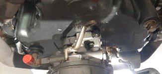
An issue came up that I have not seen a lot posted about. It is mentioned at the end of this thread in post #11 but not resolved. I am having the same issue. Any else have to deal with this? I feel like the tube is too close to the mount, and engine vibrations could cause issues. The tube is all plastic.

Van's Air Force
You are using an out of date browser. It may not display this or other websites correctly.
You should upgrade or use an alternative browser.
You should upgrade or use an alternative browser.
Shawn's -4 re-build
- Thread starter ShawnR
- Start date

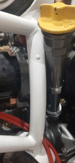
Yep! I had the same issue. I Cut the tube, then welded up a metal splice that angled it away from the engine mount. It is held in place by two screws and a dab or two of Proseal.....or was it JB Weld......An issue came up that I have not seen a lot posted about. It is mentioned at the end of this thread in post #11 but not resolved. I am having the same issue. Any else have to deal with this? I feel like the tube is too close to the mount, and engine vibrations could cause issues. The tube is all plastic.

Same issue with my RV-3B and O-320. Haven't addressed it yet.
Dave
Dave
Yep! I had the same issue. I Cut the tube, then welded up a metal splice that angled it away from the engine mount. It is held in place by two screws and a dab or two of Proseal.....or was it JB Weld......
Thanks Michael
Mine is plastic. @Roadjunkie1 Do you mean you joined the plastic base to your angle piece, then back to plastic? I found some threads that discussed extending or shortening plastic tubes. My friend suggested a metal one but it appears they are a little less common. I will try to track one down. A/S carries a replacement tube, in plastic. I have not looked too hard yet but it sounds like the best resolution. Thanks.
Having said that, I wonder if a slight bend could be put in the plastic one with the application of a heat gun. I have bent plastic conduit this way and the inspector had no issues with it, as long as not too much deformation resulted. So maybe that strategy could be put into use here. It can't be so much as to affect the path of the dip stick though....
I will report back.
Thanks
Last edited:
OK: I used a probably 2 inch piece of thin-walled tubing, the ID to match the OD of the plastic tube. I cut a notch at the halfway point of the metal tubing to get it at the correct angle (trial and error) so that the plastic tube cleared the engine mount. That notch was then welded closed. The plastic tube was cut in half an inch above the 'nut'-looking part of the plastic tube and metal splice placed on the one-inch part of the lower part of the plastic tube, but not until I had screwed the tube onto the engine to determine where the splice was to be placed. The reason being that if I had secured the splice on before, the tube would then not clear the engine mount as it was screwed into place on the engine. It angles it away aft from the original line of the tube probably 2-3 degrees, enough to now clear the mount. You will also run into the tube not clearing the mount if you hot-bend the plastic tube: as you screw it into place on the engine it will now not clear the mount. Does that make sense? Then I sealed the splice to the lower part of the plastic tube and put a small P screw midway on the lower half, then put the upper plastic section on the splice and secured it the same way. All of this was set up prior to final installation of the tube back on the engine so I wasn't having to drill holes in the splice/tube on the engine. If/when you replace the gasket at the bottom of the plastic tube, you will need to unscrew/unsecure the upper part of the plastic tube in order to remove the lower part of the plastic tube and replace the gasket. I probably have a picture of that somewhere but that has been years since it was made. Next time I have the cowling off, I'll take a picture.Thanks Michael
Mine is plastic. @Roadjunkie1 Do you mean you joined the plastic base to your angle piece, then back to plastic? I found some threads that discussed extending or shortening plastic tubes. My friend suggested a metal one but it appears they are a little less common. I will try to track one down. A/S carries a replacement tube, in plastic. I have not looked too hard yet but it sounds like the best resolution. Thanks.
Having said that, I wonder if a slight bend could be put in the plastic one with the application of a heat gun. I have bent plastic conduit this way and the inspector had no issues with it, as long as not too much deformation resulted. So maybe that strategy could be put into use here. It can't be so much as to affect the path of the dip stick though....
I will report back.
Thanks
On my 3B the oil tube is about 1/8” from hitting the motor mount but after over 200 hours it has not touched.OK: I used a probably 2 inch piece of thin-walled tubing, the ID to match the OD of the plastic tube. I cut a notch at the halfway point of the metal tubing to get it at the correct angle (trial and error) so that the plastic tube cleared the engine mount. That notch was then welded closed. The plastic tube was cut in half an inch above the 'nut'-looking part of the plastic tube and metal splice placed on the one-inch part of the lower part of the plastic tube, but not until I had screwed the tube onto the engine to determine where the splice was to be placed. The reason being that if I had secured the splice on before, the tube would then not clear the engine mount as it was screwed into place on the engine. It angles it away aft from the original line of the tube probably 2-3 degrees, enough to now clear the mount. You will also run into the tube not clearing the mount if you hot-bend the plastic tube: as you screw it into place on the engine it will now not clear the mount. Does that make sense? Then I sealed the splice to the lower part of the plastic tube and put a small P screw midway on the lower half, then put the upper plastic section on the splice and secured it the same way. All of this was set up prior to final installation of the tube back on the engine so I wasn't having to drill holes in the splice/tube on the engine. If/when you replace the gasket at the bottom of the plastic tube, you will need to unscrew/unsecure the upper part of the plastic tube in order to remove the lower part of the plastic tube and replace the gasket. I probably have a picture of that somewhere but that has been years since it was made. Next time I have the cowling off, I'll take a picture.
Ymmv
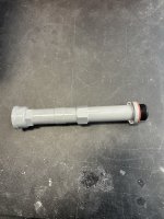
I had to shorten the oil tube for my RV4. I removed 2 1/2 inches and put it back together using JB Weld. Took some poster board and covered it with packing tape then rolled it into a tube to fit inside the oil tube so that it held the pieces together and stuck out the end.On my 3B the oil tube is about 1/8” from hitting the motor mount but after over 200 hours it has not touched.
Ymmv
Then I bonded it together making a slightly raised girdle over the two halves. 24 hours later, Sand and paint. The JB Weld is stronger than the tube!
Filed down the stamped numbers on the dip stick for oil quantity and then can etch new numbers as required.
Attachments
Thanks all for the input on the oil tube. I have not committed yet but all good solutions. I kinda like shortening. @sf3543 , any difficulty getting your hand into the opening and cap off with the shorter tube?
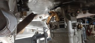
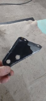
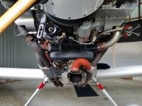
My questions today regards the engine control cables. My engine has nothing on the bottom to attach to. Previously, the builder had made a bracket which uses 2 of the oil sump bolts. It does not align very well with the throttle linkage and appeared flimsy, given its length and gauge. It also does nothing to accommodate the mixture cable. I made a new version of the bracket but I still don't like it.
I see Vans sells a nice looking bracket. My issue with that is that I have only 2 threads showing on each of the carb mount bolts, so to install the bracket and requisite additional gasket, I will be out of threads. Not sure how tough getting the carb studs out of this 50ish year old engine would be. I was hoping that the new FAB box would provide an area to attach cable supports, but, so far, it does not look like it is going to be so. Is Van's bracket or a home made version the way to go? Tackle the studs and install longer ones. Or anyone come up with a better solution?
Attachments
NopeThanks all for the input on the oil tube. I have not committed yet but all good solutions. I kinda like shortening. @sf3543 , any difficulty getting your hand into the opening and cap off with the shorter tube?
My questions today regards the engine control cables. My engine has nothing on the bottom to attach to. Previously, the builder had made a bracket which uses 2 of the oil sump bolts. It does not align very well with the throttle linkage and appeared flimsy, given its length and gauge. It also does nothing to accommodate the mixture cable. I made a new version of the bracket but I still don't like it.
I see Vans sells a nice looking bracket. My issue with that is that I have only 2 threads showing on each of the carb mount bolts, so to install the bracket and requisite additional gasket, I will be out of threads. Not sure how tough getting the carb studs out of this 50ish year old engine would be. I was hoping that the new FAB box would provide an area to attach cable supports, but, so far, it does not look like it is going to be so. Is Van's bracket or a home made version the way to go? Tackle the studs and install longer ones. Or anyone come up with a better solution?
Depending on any hoses or wires you have in that area you might have a conflict but it works ok for me.
Re the throttle bracket, I was able to use one I made so new bracket or carb studs.
This aircraft came with the standard 2 position throttle quadrant. After connecting the control for the mixture today, my friend noticed that the mixture lever on the carb was not moving fully, stop to stop. It appears that the range of the control is not enough to do so. Might need another 1/4 to half inch? Has anyone come across this? I only changed the cable and routing so the control is what was there. Nothing to suggest it was not like this before. I can have full cutoff or full rich, but not both with this setup. I think to make new hole in the quadrant arm is not feasible as I am almost at the top now. Are different arms available for carb? A shorter throw might help. I thought I might throw this question out to those familiar with the carbureted O-360.
This aircraft came with the standard 2 position throttle quadrant. After connecting the control for the mixture today, my friend noticed that the mixture lever on the carb was not moving fully, stop to stop. It appears that the range of the control is not enough to do so. Might need another 1/4 to half inch? Has anyone come across this? I only changed the cable and routing so the control is what was there. Nothing to suggest it was not like this before. I can have full cutoff or full rich, but not both with this setup. I think to make new hole in the quadrant arm is not feasible as I am almost at the top now. Are different arms available for carb? A shorter throw might help. I thought I might throw this question out to those familiar with the carbureted O-360.
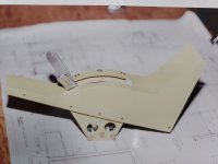
Not an uncommon thing, but not knowing how yours is made, it may or may not work. Geometry requires more throw, so remove the lever and drill a new hole farther up the throttle lever if you can, and move the clevis higher up. This increases the radius/travel distance. Some folks have to modify the carb lever if it does not have additional holes closer to the pivot. I built my own throttle quadrant (picture), so I was able to do the geometry on the bench first. You really want the mechanical stops to be the carburetor rather than within the quadrant obviously. It is possible the cable is not mid-range adjusted and the travel is limited in one direction by the clevis bottoming in the outer cable sleeve, but it sounds like you have looked at that.Re the throttle bracket, I was able to use one I made so new bracket or carb studs.
This aircraft came with the standard 2 position throttle quadrant. After connecting the control for the mixture today, my friend noticed that the mixture lever on the carb was not moving fully, stop to stop. It appears that the range of the control is not enough to do so. Might need another 1/4 to half inch? Has anyone come across this? I only changed the cable and routing so the control is what was there. Nothing to suggest it was not like this before. I can have full cutoff or full rich, but not both with this setup. I think to make new hole in the quadrant arm is not feasible as I am almost at the top now. Are different arms available for carb? A shorter throw might help. I thought I might throw this question out to those familiar with the carbureted O-360.
Attachments
Thanks for the reply @fixnflyguy Knowing that it is not uncommon is strangely reassuring. I will look to see if there is enough of a range increase with relocating the hole in the carb arm, or make a new arm for the quadrant, or.... what needs to get it to hit the carb stops.
I was able to shorten the carb arm and rebend it into the same original shape, albeit with a shorter radius. The original cable was a bowden style and that is what I was attempting to put back in. I did an ok job of securing it at both ends and all, and was happy with the install but found that the cable itself had a flex in it and was still not allowing me to achieve full deflection of the mixture arm. Definitely no "cushion" as I have come to understand the term. So I have abandoned the bowden cable and ordering a push pull cable from ACS.
Thats a better choice all the way around. I have seen a lot of Bowden cables on mixture, and a few on throttles. As an APIA, I cringe because they aren't very rubust. At one time, I advocated a light return spring on mixture arm to "rich" and "full throttle" on throttle arm, because cable failure leads to a glider.I was able to shorten the carb arm and rebend it into the same original shape, albeit with a shorter radius. The original cable was a bowden style and that is what I was attempting to put back in. I did an ok job of securing it at both ends and all, and was happy with the install but found that the cable itself had a flex in it and was still not allowing me to achieve full deflection of the mixture arm. Definitely no "cushion" as I have come to understand the term. So I have abandoned the bowden cable and ordering a push pull cable from ACS.
I wouldn’t worry about the heat muff being “way too big” the more heat the better, I would however consider replacing your old style unfiltered intake setup with a current version of the filtered air box (FAB). It’s a worthwhile upgrade.View attachment 75931coView attachment 75932
@Flyhud Question(s) for you or anyone that has input for me...
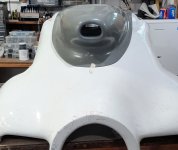
The instructions for the FAB elude to the original lower cowl being used. It says to temporarily align the FAB mounting plate, then reach in and adjust as necessary to align with the existing intake. Seeing as I am installing a new air scoop, as you did, I am wondering if there is a better one to do first. The air scoop onto the cowl or the FAB onto the carb..? If the FAB goes on the carb first, seeing as the new intake will have lots of wiggle room, should I be centering the snorkel on the airplane, trying to align the snorkel center, engine center, rollbar and vertical stabililizer......picture me standing back and lining it all up....
I noted that looking at the lower cowl, inverted on my workbench, the intake is quite offset from center to align more directly with the offset engine mount. But now, with the flexibility of a new air intake on the carb, I could probably adjust it back to center..?
And, on the practical side, the inside of the lower cowl has an oily film from 500 hours of use. Any suggestions on how to deal with this to be able to fiberglass to it? In the past, I have tried some solvents, but it appears the oil gets into the fiberglass and will resist the adhesion of new resin. Wondering if I just have not found the right cleaner yet.
Attachments
The entire carburetor and FAB are offset on the engine in most cases. Th engine mount off-set may add a little to that. The FAB can be indexed to an angle slightly to meet the inlet duct. On the -4, there isn't alot of wiggle room before the FAB contacts the cowling. I have small rubber "bumpers" on my inner cowl made from 1/8" high temperature neoprene (like the baffle material) since the engine moves a bit on start-up and shut-down. As far as fiberglass/oil contamination, that can be a battle. On the big plane composite panels at my day job, we flush with alcohol and acetone, sometimes using a vacuum bag and bleeder cloth to coax out the oils/residues. get it as clean as you can, then abraid, then clean again. See the attached photo that shows my carburetor location on the sump..its easy to see the non-centered condition.@Flyhud Question(s) for you or anyone that has input for me...
The instructions for the FAB elude to the original lower cowl being used. It says to temporarily align the FAB mounting plate, then reach in and adjust as necessary to align with the existing intake. Seeing as I am installing a new air scoop, as you did, I am wondering if there is a better one to do first. The air scoop onto the cowl or the FAB onto the carb..? If the FAB goes on the carb first, seeing as the new intake will have lots of wiggle room, should I be centering the snorkel on the airplane, trying to align the snorkel center, engine center, rollbar and vertical stabililizer......picture me standing back and lining it all up....
I noted that looking at the lower cowl, inverted on my workbench, the intake is quite offset from center to align more directly with the offset engine mount. But now, with the flexibility of a new air intake on the carb, I could probably adjust it back to center..?
And, on the practical side, the inside of the lower cowl has an oily film from 500 hours of use. Any suggestions on how to deal with this to be able to fiberglass to it? In the past, I have tried some solvents, but it appears the oil gets into the fiberglass and will resist the adhesion of new resin. Wondering if I just have not found the right cleaner yet.
Attachments
I aligned my lower cowl scoop as close to the centerline as possible, I used measurements and a laser to get it as good as I could, it’s not an exact science. You can cleco the scoop onto the cowl and if you need to move it around, a few extra holes in the fiberglass are easy to fix. After I was satisfied with the position of the cowl scoop on the cowling, I aligned the fab inlet to the scoop. My original cowling scoop was like yours, the scoop was offset and looked wonky if you looked at the cowl directly from the front. You can see in the photos there is a slight offset on the top FAB plate to bring the snout back to center.@Flyhud Question(s) for you or anyone that has input for me...
The instructions for the FAB elude to the original lower cowl being used. It says to temporarily align the FAB mounting plate, then reach in and adjust as necessary to align with the existing intake. Seeing as I am installing a new air scoop, as you did, I am wondering if there is a better one to do first. The air scoop onto the cowl or the FAB onto the carb..? If the FAB goes on the carb first, seeing as the new intake will have lots of wiggle room, should I be centering the snorkel on the airplane, trying to align the snorkel center, engine center, rollbar and vertical stabililizer......picture me standing back and lining it all up....
I noted that looking at the lower cowl, inverted on my workbench, the intake is quite offset from center to align more directly with the offset engine mount. But now, with the flexibility of a new air intake on the carb, I could probably adjust it back to center..?
And, on the practical side, the inside of the lower cowl has an oily film from 500 hours of use. Any suggestions on how to deal with this to be able to fiberglass to it? In the past, I have tried some solvents, but it appears the oil gets into the fiberglass and will resist the adhesion of new resin. Wondering if I just have not found the right cleaner yet.


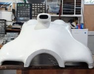
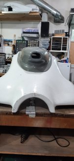
I am getting ready to cut the old cowling but looking at @Flyhud 's cowling, there seems to be large gaps to fill on mine. I am fairly inexperienced with making these sort of mods. I would think that forcing the old cowl (after it is cut) into a position suitable for fiberglassing the 2 together is not a good idea. I have been told that some reforming can be done with a little heat. Or do I cut way back and add many new layers of glass to get closer to the new cowl? My plane is circa 1984 so I am wondering if cowls were different, in shape, back then? Once I make some cuts, things could get easier to manipulate into place. But thought I might ask all first before I go doing something I will regret....
Attachments
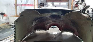
Build up/fill the big gaps with bondo until its smooth and lays flat before you cut it. Glass over the filler first and then make your cut, grind out all the filler from the inside and then add more lay ups to the inside. Drill some holes around the perimeter and cleco it in place before you cut it so it goes back in the same place, it gets kinda floppy after you cut it. Heat won’t do any good with gaps that big.I am getting ready to cut the old cowling but looking at @Flyhud 's cowling, there seems to be large gaps to fill on mine. I am fairly inexperienced with making these sort of mods. I would think that forcing the old cowl (after it is cut) into a position suitable for fiberglassing the 2 together is not a good idea. I have been told that some reforming can be done with a little heat. Or do I cut way back and add many new layers of glass to get closer to the new cowl? My plane is circa 1984 so I am wondering if cowls were different, in shape, back then? Once I make some cuts, things could get easier to manipulate into place. But thought I might ask all first before I go doing something I will regret....
The first thing I would do is mount the cowl back on the plane and then fit the inlet by clecoing it on.I am getting ready to cut the old cowling but looking at @Flyhud 's cowling, there seems to be large gaps to fill on mine. I am fairly inexperienced with making these sort of mods. I would think that forcing the old cowl (after it is cut) into a position suitable for fiberglassing the 2 together is not a good idea. I have been told that some reforming can be done with a little heat. Or do I cut way back and add many new layers of glass to get closer to the new cowl? My plane is circa 1984 so I am wondering if cowls were different, in shape, back then? Once I make some cuts, things could get easier to manipulate into place. But thought I might ask all first before I go doing something I will regret....
This allows the lower cowl to be in its final position and may reduce the gap you are seeing significantly, since the cowl may be sagging when just sitting on the ground. I’d at least check this before doing a lot of filling, etc. It could save you a lot of work.
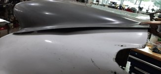
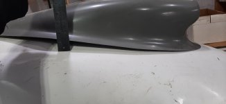
I did put the cowling back on the fuselage and there was not a lot of difference that I could see, although some. It was well worth doing though to verify. When, inverted on the bench, I have a wire holding the two sides about the width of the fuselage, so I think that that helps out with test fitting. I have been building up the surface with bondo so as to close some of the gaps between the old cowl and new intake. In the center, it was at least an inch to fill. The photo is no where close of course (had to go get more bondo) but it is showing me that I have some decisions to make. Do I build it up so that the new look is more one gentle curve as shown on the left in the photo, or try to follow the original contours of the -4 cowling, which is a couple of curves on the right. In @Flyhud 's, it looks like it is one gentle curve, not two. I also found another well documented intake install online (@AJ85WA ) and his looks like it is one gentle curve (although it is on a -6 so maybe a different cowl shape altogether) Once I get the surface that contacts the new intake to a shape that it is ready for fiberglass, I will worry about the final overall shape. It might be better to use some foam to get closer. I seem to be using a lot of bondo to get the shape needed. And I noted it builds quite a bit of heat as it cures, so I am building it up in layers. The photo does not show it very well, but unless my old cowling is a very different shape than others, you probably know what I am seeing. Anyone with input for me as I fumble along? ")
Thank you
Thank you
Attachments
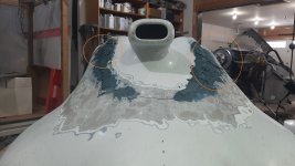
Plasticine type modelling clay works very well for moulding. It is inexpensive and easy to work with and the shape can be changed quickly by slicing off or adding on more. After the fiberglass has been laid up, the plasticine is removed by scraping out and cleaning up with mineral spirits or turpentine. Craft stores sell the modelling clay in 1 lb blocks and it can be reused. I used plasticine to mould all of the intersection fairings and it was much less work and quicker than bondo.I did put the cowling back on the fuselage and there was not a lot of difference that I could see, although some. It was well worth doing though to verify. When, inverted on the bench, I have a wire holding the two sides about the width of the fuselage, so I think that that helps out with test fitting. I have been building up the surface with bondo so as to close some of the gaps between the old cowl and new intake. In the center, it was at least an inch to fill. The photo is no where close of course (had to go get more bondo) but it is showing me that I have some decisions to make. Do I build it up so that the new look is more one gentle curve as shown on the left in the photo, or try to follow the original contours of the -4 cowling, which is a couple of curves on the right. In @Flyhud 's, it looks like it is one gentle curve, not two. I also found another well documented intake install online (@AJ85WA ) and his looks like it is one gentle curve (although it is on a -6 so maybe a different cowl shape altogether) Once I get the surface that contacts the new intake to a shape that it is ready for fiberglass, I will worry about the final overall shape. It might be better to use some foam to get closer. I seem to be using a lot of bondo to get the shape needed. And I noted it builds quite a bit of heat as it cures, so I am building it up in layers. The photo does not show it very well, but unless my old cowling is a very different shape than others, you probably know what I am seeing. Anyone with input for me as I fumble along?
Thank you
Thanks @PaulvS That sounds like what I will do after I get the actual mating surface ready. We have a Michael's and looks like they carry it.Plasticine type modelling clay works very well for moulding. It is inexpensive and easy to work with and the shape can be changed quickly by slicing off or adding on more. After the fiberglass has been laid up, the plasticine is removed by scraping out and cleaning up with mineral spirits or turpentine. Craft stores sell the modelling clay in 1 lb blocks and it can be reused. I used plasticine to mould all of the intersection fairings and it was much less work and quicker than bondo.
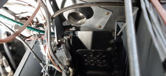
I am back to working on the -4. Have the new air inlet on, and FAB installed. When I started looking at the cable routes, I found the area where the builder put the cab heat inlet is quite congested. I cannot find that drawing, but from info found online, it looks standard in the 4, "tunnel". I am wondering if there is any reason I should not move it....? I am considering the area above the shelf over the right rudder pedal. I could easily then route warm air either down or directly back to the pilot. Anyone have input? The original control valve was very poorly done so I made up a new one similar to the angle one sold for other models. I think it will work ok in the new location but is tight in the old location as it sits within a "Y" on the engine mount. It seems with the carb control cables, new FAB box and exhaust, the old location is not a great spot. It would mean another hole in the firewall, but patching the old one with a piece of stainless. What do you all think?


Shawn,Hi all
In a couple of other threads, I started asking questions about RV-4's before I bought one, then found one that was complete and flying, with a 180 hp in it, which was appealing. It was not so nice that I would be afraid to take things apart and start making changes. I need to learn about how these are built, and update it to what I might want (not sure what that is yet, but that will be part of the journey).
Happy to say that I received my new ride last week. I will need to get checked out for insurance and it needs those rear rudder pedals I mentioned in other threads. Since our flying season is almost over, I won't be airborne in it again this year. The seller did take me up when he first brought it here for me to see. As much as I have been in other RV's, I think I might have had the RV grin for the first time when I realized I might actually own one one day.
This thread was the start of my questions, in case some of you feel like we discussed this before, but now I think I will put updates to the rebuild process into this thread here to avoid a bunch of random threads going with my many questions that I anticipate.
I will be looking forward to input from those of you with experience in owning, building and or flying them. The plane first flew in 1984 so if I understand correctly, there will be a few updates that I can do. As I sat in it, looking around for ideas and changes that I might make, I felt overwhelmed with the idea of starting one from scratch! My hat is off to those of you with the focus and determination to do so. I view my plane as an ultimate fast build. It has flown with 500 hours, so tested, yet will need some updates and parts possibly redone to make it nice(r). I am hoping to have it airborne in the spring. Up here in Northern Canada, there is not a lot of flying off of grass strips anyways in the winter, so it will be a good time to get er done.
Attached is a few photos to give you an idea of what I am working with. I have always liked fixing up old stuff so will see what I can do with a homebuilt aircraft. I am not expecting to make it into a show plane, but do want something I am proud of. I think there is a lot of (enjoyable) work ahead of me.
Cheers all,
Shawn
")
Good for you.
You will love it even more after you "make it yours".
I also bought mine flying (c.1996).
1. Put it on a diet. Found ways to reduce weight.
2. began updating the round dials.
3. PMag
4. removed vacuum pump and plumbing.
5. Updated creature comforts (fresh leather seats)
6. fresh 5-point Crow harnesses
Happy Landings,
Daddyman58
Thanks @Daddyman58. Work on it is sporadic....but maybe one day, it will fly again.
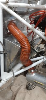
A friend came over today and we discussed the cabin heat. He agreed that the proposed location is better to reduce congestion in the lower firewall, and it makes running the scat tubing much easier. So that is where I am going with it. I should be able to post some photos soon.
A friend came over today and we discussed the cabin heat. He agreed that the proposed location is better to reduce congestion in the lower firewall, and it makes running the scat tubing much easier. So that is where I am going with it. I should be able to post some photos soon.
Your proposed new location is exactly where the valve is in my RV4. The valve itself is the stainless one you can purchase. I recommend a flange facing you inside the plane. I put a short (4 inches) piece of SCAT on it which moves the majority of the heat to you while still warming your feet. Without the SCAT, you will have very warm feet but not much heat anywhere else.