my Dynon AP does a great job in VS mode but in IAS it's over controlling the pitch and oscilating. I set VS for 1000 fpm climb and monitor IAS closely to stay above 100 kts. I'm usually at the cruise altitude before I need to lower the VS rate. not ideal but I'm not sure how to make the IAS climb more stable.Was taught to use IAS mode, so the AP will always keep the aircraft flying fast enough and will lower the nose if it has to

Van's Air Force
You are using an out of date browser. It may not display this or other websites correctly.
You should upgrade or use an alternative browser.
You should upgrade or use an alternative browser.
Some questions - climb and CHT.
- Thread starter JohnStirling
- Start date

Can you not adjust the AP?my Dynon AP does a great job in VS mode but in IAS it's over controlling the pitch and oscilating. I set VS for 1000 fpm climb and monitor IAS closely to stay above 100 kts. I'm usually at the cruise altitude before I need to lower the VS rate. not ideal but I'm not sure how to make the IAS climb more stable.
In my other airplane (Bristell running Garmin G3X) my AP was terrible when I took possession. It would porpoise and carry on, so I spent a good couple of hours calibrating it in flight, and had it dialled in where it was rock solid.
I have not had a chance to assess the RV too much, the conditions have been ordinary, so it is hard to tell how good the AP is doing when you are being tossed like salad on the climb! LOL!
You mean those engineers at Lycoming that designed the H2AD?Or perhaps the engineers who designed the engine knew what they were doing, the 500 limit and the other limits in the manual are sensible, ...
I can talk trash like that because I have an H2AD. Actually not a bad engine now, but the engineers seriously got the cam/lifters wrong initially.
Also the proud owner of an H2AD.You mean those engineers at Lycoming that designed the H2AD?
I can talk trash like that because I have an H2AD. Actually not a bad engine now, but the engineers seriously got the cam/lifters wrong initially.

I think you’re sort of making my point though. When the Lycoming engineers screwed up the H2AD, that fact became fairly obvious pretty quickly because of experience in the field. There’s no similar data suggesting their max CHT recommendations are wrong, and it’s been what, 50 years? 70?
Some ap’s have different gain settings for vs and ias. Worth looking into. Both my grt and my garmin are very stable in both modes, though I rarely using vs for climbs.my Dynon AP does a great job in VS mode but in IAS it's over controlling the pitch and oscilating. I set VS for 1000 fpm climb and monitor IAS closely to stay above 100 kts. I'm usually at the cruise altitude before I need to lower the VS rate. not ideal but I'm not sure how to make the IAS climb more stable.
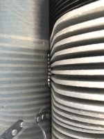
OK lads. Doing some investigate work and having a really good look at these baffles and have a look at this. Found a VERY large gap at the back of Cyl 3. Watch the below - let me know what you think? Should it be sealed? And if so - How - It is a massive gap.
I was taught many years ago that if otto is driving the bus, best practice would be to climb on an airspeed and descend on a vertical speed.my Dynon AP does a great job in VS mode but in IAS it's over controlling the pitch and oscilating. I set VS for 1000 fpm climb and monitor IAS closely to stay above 100 kts. I'm usually at the cruise altitude before I need to lower the VS rate. not ideal but I'm not sure how to make the IAS climb more stable.
I say that not because of anything related to your oscillating issue, but because there are scenarios where it would just keep pitching itself up into a stall while trying to achieve an unobtainable vertical speed.
I'll admit that those scenarios are probably unlikely in an RV; carrying a load of ice, etc. but it's something to think about.
OK lads. Doing some investigate work and having a really good look at these baffles and have a look at this. Found a VERY large gap at the back of Cyl 3. Watch the below - let me know what you think? Should it be sealed? And if so - How - It is a massive gap.
John, your video died, but it's a safe bet the large gap is located at the no-fin section of the cylinder base, down by the big nut at the bottom rear. If so, there is a tab on the baffle tin which was to be bent forward and upward. However, even when installed correctly, it's not very air tight, and hard to seal with the squeeze tube.
Here's a trick. Get a little square of 9oz fiberglass cloth. Squirt some Permatex UltraBlack on it, then sandwich it between two sheets of 4 mil plastic. Work the silicone into the fabric. When saturated, cut a section to fit the gap. Peel one side of the plastic, position the saturated fabric down in the gap so it sticks to the tin and cylinder, peel the top plastic sheet, allow to cure.
Don't feel bad. This was the RV-1after a whole heap of good people worked on it:

And the same at the front of cyl #2:

Last edited:
John, your video died, but it's a safe bet the large gap is located at the no-fin section of the cylinder base, down by the big nut at the bottom rear. If so, there is a tab on the baffle tin which was to be bent forward and upward. However, even when installed correctly, it's not very air tight, and hard to seal with the squeeze tube.
Here's a trick. Get a little square of 9oz fiberglass cloth. Squirt some Permatex UltraBlack on it, then sandwich it between two sheets of 4 mil plastic. Work the silicone into the fabric. When saturated, cut a section to fit the gap. Peel one side of the plastic, position the saturated fabric down in the gap so it sticks to the tin and cylinder, peel the top plastic sheet, allow to cure.
Don't feel bad. This was the RV-1after a whole heap of good people worked on it:
And the same at the front of cyl #2:
THAT is exactly the hole I have. LOL!
Video is fixed! Sorry about that.
Yep! I need to fill that gap with something before trying to pump it full of silicone! LOL!
Last edited:
Well there's another 4 or 5 degrees I'd wager.OK lads. Doing some investigate work and having a really good look at these baffles and have a look at this. Found a VERY large gap at the back of Cyl 3. Watch the below - let me know what you think? Should it be sealed? And if so - How - It is a massive gap.
John, first off, after watching your video, I think "what a cool accent".
Secondly, those tabs around the base of the cylinders are absolutely one of the most overlooked areas for air bypassing the fins. Since the engine typically comes with those tabs like that, many people think they're supposed to be like that. If it's not a gap by a cooling fin, seal it up. Dan referenced one way to do it above. That's probably more elegant than my method of putting a glob of RTV on a wooden dowel and using it like an applicator extension. But either method works.
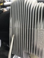
In your video, you referenced the #3 trick. This is a separate issue from the tabs at the base of the cylinders. The manufacturing process on the back side of the cylinder creates little dams between the fins that restrict air flow to the back and underside. Because of how the baffles and cylinders are arranged, #3 is usually the one affected the most. Look at what the screwdriver is pointing to below. You can either put a washer in the back corner of the baffle where the #8 screw goes to create a gap, or you can create a cut-out diversion area that lets air circulate around. That's what I did, as shown in the other pic. There's much written on this site showing how this works. It takes a little effort, but it's worth it. At least in my opinion.
Secondly, those tabs around the base of the cylinders are absolutely one of the most overlooked areas for air bypassing the fins. Since the engine typically comes with those tabs like that, many people think they're supposed to be like that. If it's not a gap by a cooling fin, seal it up. Dan referenced one way to do it above. That's probably more elegant than my method of putting a glob of RTV on a wooden dowel and using it like an applicator extension. But either method works.
In your video, you referenced the #3 trick. This is a separate issue from the tabs at the base of the cylinders. The manufacturing process on the back side of the cylinder creates little dams between the fins that restrict air flow to the back and underside. Because of how the baffles and cylinders are arranged, #3 is usually the one affected the most. Look at what the screwdriver is pointing to below. You can either put a washer in the back corner of the baffle where the #8 screw goes to create a gap, or you can create a cut-out diversion area that lets air circulate around. That's what I did, as shown in the other pic. There's much written on this site showing how this works. It takes a little effort, but it's worth it. At least in my opinion.
Attachments
John, first off, after watching your video, I think "what a cool accent".
Secondly, those tabs around the base of the cylinders are absolutely one of the most overlooked areas for air bypassing the fins. Since the engine typically comes with those tabs like that, many people think they're supposed to be like that. If it's not a gap by a cooling fin, seal it up. Dan referenced one way to do it above. That's probably more elegant than my method of putting a glob of RTV on a wooden dowel and using it like an applicator extension. But either method works.
In your video, you referenced the #3 trick. This is a separate issue from the tabs at the base of the cylinders. The manufacturing process on the back side of the cylinder creates little dams between the fins that restrict air flow to the back and underside. Because of how the baffles and cylinders are arranged, #3 is usually the one affected the most. Look at what the screwdriver is pointing to below. You can either put a washer in the back corner of the baffle where the #8 screw goes to create a gap, or you can create a cut-out diversion area that lets air circulate around. That's what I did, as shown in the other pic. There's much written on this site showing how this works. It takes a little effort, but it's worth it. At least in my opinion.
Ahahah thanks mate. That the Aussie accent. lol.
I’m working on closing all the gaps. The washer thing - so many conflicting versions. And where does the washer itself go??
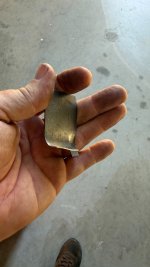
Anyways. I’m actually away from the machine for a few days but will get that area blocked up. Made a metal piece that will be glued on, and the gaps filled.
Along with some others and then will fly and see how it goes.
A quick search revealed some pretty good pics. Take a look: https://vansairforce.net/threads/baffle-mod.37835/Ahahah thanks mate. That the Aussie accent. lol.
I’m working on closing all the gaps. The washer thing - so many conflicting versions. And where does the washer itself go??
Anyways. I’m actually away from the machine for a few days but will get that area blocked up. Made a metal piece that will be glued on, and the gaps filled.
Along with some others and then will fly and see how it goes.
There's a mix of parallel valve and angle valve engines in that thread, but the basic concept is the same. Dan Horton explains what the issue is and several possible fixes. I used the method outlined in Post #5 instead of the "washer trick". For the parallel valve engine, look at Post #18 to see where the washer goes between the cylinder head threaded hole on the right and the baffle (baffle not shown). There may be better pics out there, but this will get you started.
A quick search revealed some pretty good pics. Take a look: https://vansairforce.net/threads/baffle-mod.37835/
There's a mix of parallel valve and angle valve engines in that thread, but the basic concept is the same. Dan Horton explains what the issue is and several possible fixes. I used the method outlined in Post #5 instead of the "washer trick". For the parallel valve engine, look at Post #18 to see where the washer goes between the cylinder head threaded hole on the right and the baffle (baffle not shown). There may be better pics out there, but this will get you started.
Yep. I have had a good read of that thread. I like the method of cutting a piece out and creating an indented area. Very neat solution.
Although that would required me to remove the rear plates etc, and not sure I am ready for that. Lol. Same with bashing a dent. Still need to remove it.
Still don’t understand where the washer goes. Not that I’m actually looking to do it. I’ll plug all the other holes first and see how it goes.
Okay, the washer trick is the quick and easy way to increase airflow around the back side of the #3 cylinder fins. You can put a little RTV on that area if you want to eliminate the path of wasted air there. Look at the photo below that I copied from BillL. The screw goes in the hole on the right and holds the rear baffle in place. The washer goes between the cylinder head and the baffle. It's a five minute job to try it.
Attachments
Ahhh.. I see that now. Hmm.. OK.
Well, I will plug all of my holes first, and see how it goes.
I have already plugged a number of holes that were just wasting air! Some serious ones too! LOL!
Well, I will plug all of my holes first, and see how it goes.
I have already plugged a number of holes that were just wasting air! Some serious ones too! LOL!
UPDATE
so I spent the afternoon with a flashlight plugging all the gaping holes around my baffling. Wow. There was LOTS.
I had light streaming in everywhere. I ended up using an entire tube of Ultrablack it was that bad.
Had a massive gap around the engine mount hole on one side. Really bad holes around the lower sections where the baffles curve around the cylinders - especially the sides of those curved bits.
Had big gaps around the front too.
Anyways. Plugged them all, and now just need some better weather (maybe Tuesday) to take her for a run.
David Bell
Well Known Member
Don’t forget your statin and bp med on climb out
Excluding the negative effects to climb performanceStay away from Statins…
") , I am truly curious to understand your reservations here. Maybe a link to some research you respect on the subject? Like many in this country, my Dr recommends them and finding real data on potential negative effects is hard to find without bias or "follow the leader" mentality.
, I am truly curious to understand your reservations here. Maybe a link to some research you respect on the subject? Like many in this country, my Dr recommends them and finding real data on potential negative effects is hard to find without bias or "follow the leader" mentality.OK. Update.
So took her up today and I can already see a difference with the efforts I put in. I did 3 test runs. OAT at 27c on the ground.
First was to just climb out at 90kts and see how hot she got. It topped out at 420 on Cyl3 all the way to 4500.
Went around again for another go. Landed. Let the temps warm up again, like I was doing a runup etc. (Starting around 360 during taxi. )
Second climb was 120kts all the way. Cyl 3 hit 410 and the rest just under 400.
Third one was to climb at 90 to about 1500AGL (simulating that I need a steep climb out) and then roll her nose over and let her climb out at 120. Again, Cyl 3 never went past 410.
Cruised at TAS of 155, and it sat around 370s, 380s.
So far - happy with the outcomes. I will go up again tomorrow and play a bit more, but I am liking what I have achieved with just a little bit of effort.
OK. Update.
So took her up today and I can already see a difference with the efforts I put in. I did 3 test runs. OAT at 27c on the ground.
First was to just climb out at 90kts and see how hot she got. It topped out at 420 on Cyl3 all the way to 4500.
Went around again for another go. Landed. Let the temps warm up again, like I was doing a runup etc. (Starting around 360 during taxi. )
Second climb was 120kts all the way. Cyl 3 hit 410 and the rest just under 400.
Third one was to climb at 90 to about 1500AGL (simulating that I need a steep climb out) and then roll her nose over and let her climb out at 120. Again, Cyl 3 never went past 410.
Cruised at TAS of 155, and it sat around 370s, 380s.
So far - happy with the outcomes. I will go up again tomorrow and play a bit more, but I am liking what I have achieved with just a little bit of effort.
That’s good, first simple change made - next is the ‘Dan Horton’ style mod on the aft baffle of #3 cylinder.
Followed by the baffles seals in the front of engine & other poorly sealed areas.
Yep. Amazing how just some little things make a big difference.
Good! Now try the washer trick on #3 and watch that cylinder CHT drop down to where the other cylinders are. Use some dental floss to hold the washer from above while you push the washer into place between the baffle and the rear of the cylinder head with a screwdriver or a flat piece of metal. Capture it with the #8 screw from the rear, pull the floss out, and go flying again. If you like the results, you can always modify the rear baffle later on for a more efficient way to achieve the same result. But dropping the washer in from the top is a quick and easy way to see if improvements can be made.
And as Jake stated, look at previous posts to see how improvements can be made on other baffles & seals to ensure good cooling. And while many will say the numbers you're seeing aren't detrimental to the engine, it is an issue that you want to improve upon. Clearly, many others want to see what you want to see, or this thread wouldn't be approaching 180 posts.
And as Jake stated, look at previous posts to see how improvements can be made on other baffles & seals to ensure good cooling. And while many will say the numbers you're seeing aren't detrimental to the engine, it is an issue that you want to improve upon. Clearly, many others want to see what you want to see, or this thread wouldn't be approaching 180 posts.
Lot's of good information. Seal the baffles. However, don't cut holes or expand exit area on the cowling if your cruise numbers are good. Nothing is for free and if you increase the exit area, you increase cooling drag. These cowls are like fixed pitch props: if you optimize for cruise, climb suffers. So, if you keep your cowling tuned for cruise, you need to climb at a minimum of 120KIAS to create more cooling for the engine. If you increase the exit area you can climb slower, but at cruise you will create more cooling drag than needed which will affect airspeed. The only answer is inflight adjustable cowl flaps that increase your exit area on climb, and then close for cruise. It is a widely accepted technique to climb at 120+KIAS in our RV's.
Good morning Lads,
So, went up again today for a play, first thing this morning. OAT on the ground was 19c.
Took off and climbed at 90 for the first 2000ft. CHTs all under 400. Rolled her to 110, and let it go all the way to 8500, with a great rate of climb.
I am pretty happy now, and can now take my time to go and tidy up a few things, and maybe try the washer trick, to see what that does.
I just want to say thank you to everyone that contributed to this post, and who contacted me directly with advice etc. Your input is so valuable to someone like me who is new to the RV world.
I am loving getting use to this machine, and it is quite a bit different from the ROTAX machine I have been sitting behind.
I will continue to update with progress as I go.
Thanks again everyone
MERRY XMAS!!!
Good morning Lads,
So, went up again today for a play, first thing this morning. OAT on the ground was 19c.
Took off and climbed at 90 for the first 2000ft. CHTs all under 400. Rolled her to 110, and let it go all the way to 8500, with a great rate of climb.
I am pretty happy now, and can now take my time to go and tidy up a few things, and maybe try the washer trick, to see what that does.
I just want to say thank you to everyone that contributed to this post, and who contacted me directly with advice etc. Your input is so valuable to someone like me who is new to the RV world.
I am loving getting use to this machine, and it is quite a bit different from the ROTAX machine I have been sitting behind.
I will continue to update with progress as I go.
Thanks again everyone
MERRY XMAS!!!
It’s always interesting to see if we can quantify the effect of baffle leaks. In your first post you talked about keeping it below 420. After you improved the baffles you can now keep it below 400. Does that imply you reduced your maximum CHT 20 degrees? same rate of climb? same OAT?
Good morning Lads,
So, went up again today for a play, first thing this morning. OAT on the ground was 19c.
Took off and climbed at 90 for the first 2000ft. CHTs all under 400. Rolled her to 110, and let it go all the way to 8500, with a great rate of climb.
I am pretty happy now, and can now take my time to go and tidy up a few things, and maybe try the washer trick, to see what that does.
I just want to say thank you to everyone that contributed to this post, and who contacted me directly with advice etc. Your input is so valuable to someone like me who is new to the RV world.
I am loving getting use to this machine, and it is quite a bit different from the ROTAX machine I have been sitting behind.
I will continue to update with progress as I go.
Thanks again everyone
MERRY XMAS!!!
IMO you should go directly to the mod as I suggested previously, it has a much better impact - the washer ‘trick’ is just that, it has an lower/poorer effect than the ‘mod’.
 Jake.
Jake.Ps - btw - With all the RVs (54) I’ve worked on I’ve never seen the need to 1. Fabricate a plenum or 2. Install cowl flaps. In my aircraft the CHTs are typically in the 300-305 F range at OAT ~ 18 deg C or 305-325 F range at OAT ~ 20-27 deg C.
Last edited:
It’s always interesting to see if we can quantify the effect of baffle leaks. In your first post you talked about keeping it below 420. After you improved the baffles you can now keep it below 400. Does that imply you reduced your maximum CHT 20 degrees? same rate of climb? same OAT?
obviously it will depend greatly on outside air temp, but essentially yes. The minor work I have done so far has made a difference significant enough to notice.
Yep! I will keep working on it, and I am sure I can get it down more.IMO you should go directly to the mod as I suggested previously, it has a much better impact - the washer ‘trick’ is just that, it has an lower/poorer effect than the ‘mod’.
Ps - btw - With all the RVs (54) I’ve worked on I’ve never seen the need to 1. Fabricate a plenum or 2. Install cowl flaps. In my aircraft the CHTs are typically in the 300-305 F range at OAT ~ 18 deg C or 305-325 F range at OAT ~ 20-27 deg C.
Cyl 3 is still the hottest (followed closely by Cyl4) wich has changed as the 1 and 2 are cooling better now to make it the 2nd hotest) But in the cruise at full noise, and leaned back, they are all sitting in the 370s. So it appears the temps are all a bit closer now.
I reckon I can do better, but I have bought myself some time to be able to fly comfortably until I can find some serious time to redo the rubber baffles. (going to need a bit of time for that one. LOL!)
So for those following at home, I have another update.
As you know I have been plugging all the holes in and around my baffles. Did the underside a few days ago and it certainly has an affect. Climbing out now does not get much over 400. Might hit 410 if I pull its nose up for a higher climb rate. Happy with that.
What I did notice though was CHTs were very scattered in the cruise. Anywhere from 350 to 390 across the 4 cylinders. Even after all the holes I plugged, they could still be a bit out.
SO…. I decided (out of curiosity more than anything else) to do the washer mod an see what happens. Well, the results are in.
I put the washer in and plugged up the holes so it just allowed air over an through the fins. And it had good effect.
Climb out still great. 405 today.
But the cruise is what seems to have been affected.
Went for a Nav 1 hour away and back) and had it dialled in. CHTs all sat within 5 degrees of each other. 377 to 382. Sitting at 155 knots.
I have new baffle runners coming and they will be worked on, so should see more of an improvement after that done. But happy.
Was a beautiful day to fly today.
Attachments
Sure would be *useful* and *informative* if we had, you know, actual data plots to look at (e.g., SavvyAnalysis).
Last edited:
Very much so. You probably want to use an overlapping segmented approach. If you could see it from the inside, (ideally) the finished product would look like this.
View attachment 103918
So just going back through all the tips in this thread, and I am curious about your photo. Is that one piece of rubber around the rear of the starter ring?
I have tried today, and there is no way I can use one piece. I can, but then the curl is too great and it will sit way too low to be affective.
Can you elaborate on this setup?
I did this recently and summoned the baffling gods. Implemented the baffling cylinder #2,3,and 4 mods as well. We'll see in a few months if it works
Great looking baffles! And again, you look like you did one continuous bit around the starter ring, which I just can't make happen. The curl is too low.

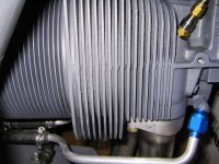
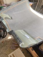
This is the segmented section behind the starter ring. It is three pieces. It looks awful with the cowl off, but is conformed so it seals very well. Here are a couple of pictures. Note that I was going through a progressive replacement of the seals, so there was (and still is) a mix of different materials.So just going back through all the tips in this thread, and I am curious about your photo. Is that one piece of rubber around the rear of the starter ring?
I have tried today, and there is no way I can use one piece. I can, but then the curl is too great and it will sit way too low to be affective.
Can you elaborate on this setup?


Be sure to check that jam nut on the prop control rod-end bearing.This is the segmented section behind the starter ring. It is three pieces. It looks awful with the cowl off, but is conformed so it seals very well.
Here are a couple of picturesView attachment 106208View attachment 106209 with the cowl off.
Thanks, Mel.Be sure to check that jam nut on the prop control rod-end bearing.
You mean as you see here?Out of curiosity - do you have the upper cowling inlet ramps installed?
This is the segmented section behind the starter ring. It is three pieces. It looks awful with the cowl off, but is conformed so it seals very well. Here are a couple of pictures. Note that I was going through a progressive replacement of the seals, so there was (and still is) a mix of different materials.
Thanks! I am going to have to segment too - Just no way to get it to curve all the way around.
Thanks for the pics. Should get it done today.
I didn't see your picture attached...maybe it's my browser.You mean as you see here?
but this is what I was asking about:
 and
and
(from the RV-14 instructions....)
Yes! I have the ramps each side.
How do they "look?"Yes! I have the ramps each side.
In the -7/8/9/10/14, Van's includes the ramps as part of the cowling sub-kit; one of the gothas in the 7/8/9 was needing to fill/seal off the side/ends of these ramps to keep the airflow from tripping and becoming turbulent in these areas.
Yeah, mine are all filled in
Any chance you have a photo of the "ramps inside the cowling that help with cooling?"Okay- looking at your picture, you see how there are wear marks on the rubber baffle material where air loads have pushed it up into the inside of the cowl? Thats what you want to see. It appears to me that you have a pretty good interface all the way around with the exception of the area behind the starter ring gear where it look like there might be some room for improvement.
Also, the inside of your upper cowl is supposed to have ramps built into it to help direct the airflow. It wouldn't be unheard of for those to have never been installed, or if they are installed but don't have a good interface to the baffle rubbers for them to provide a significant leak path for air to go where it isn't doing any good.
Not saying that either of these are for sure your problem, just stuff to check
I don't think it's an error. I did a sawtooth climb test a few months back in my RV8 (IO360, FP Catto 3 blade) and had the same results. I was surprised and thought maybe it had to do with the higher RPM available at full throttle at the higher speed?I thought that was carsons speed.
I don’t really know and definitely not trying to start a debate. Happy to say this was just an error on my part. I found it odd also, as i thought there could only be one Vy speed. But as i said, i get really good climb performance at that 140.
