Pictures?My cylinders look worse then that - still going strong 20+ years and 1500 hours later. People want perfection, but these engines are far from perfect. They are relatively crude, imperfect machines. Antique technology really. You will encounter all sorts of problems. You just don't want catastrophic problems, but that is extremely unlikely.

Van's Air Force
You are using an out of date browser. It may not display this or other websites correctly.
You should upgrade or use an alternative browser.
You should upgrade or use an alternative browser.
Have I ruined my new engine?
- Thread starter IO390
- Start date

Thay is really bad on the ring clearance and could explains all of the wear. Was there enough clearance to get the ring to sit flush with the piston wall?. Did you measure the ring end gap up in the choke area? .007 is what I remember the minimum being. 0030-0045 down at the bottom. This is just as important as the land clearance.That's what we did to measure the clearance. I had the benefit this evening of a very experienced mechanic being in the hangar, and he spent a good couple of hours inspecting all the various dimensions of the cylinder and piston. The clearance on these new pistons was so small a .0015 feeler would not fit.
Also the new Superior piston was 0.014 out of round - I'm surprised they can manufacture something this poorly, or is this intentional?
I don’t really understand how you can get a piston that far out of round. Must be cnc and not a lathe. Definitely serious QA issues at superior. It is NOT specified for that. Supposed to be round.
Last edited:
Looked more closely at the rings in today’s pics. Notice how the black heat marks get bigger as you get closer to the ring ends and how the wear is very concentrated at the very top edge? This seems to imply too small of a rig end gap.
Hard to tell from pic, but it looks like the rings bevel is facing up. I vaguely recal these get installed with the bevel down. If installed upside down, it will prevent the ring from going in deep enough into the land and bind before the OD of the ring gets behind the piston OD. The lyc SI is clear that you must insure that the ring settles into the land enough that the ring od surface is slightly set back from the piston od surface. This could explain why the clearance was so small. Improper orientation would also cause the ring to tip down just a bit and explains why the ring is only contacting the wall at the extreme top edge of the ring, as shown in your pics.
Hard to tell from pic, but it looks like the rings bevel is facing up. I vaguely recal these get installed with the bevel down. If installed upside down, it will prevent the ring from going in deep enough into the land and bind before the OD of the ring gets behind the piston OD. The lyc SI is clear that you must insure that the ring settles into the land enough that the ring od surface is slightly set back from the piston od surface. This could explain why the clearance was so small. Improper orientation would also cause the ring to tip down just a bit and explains why the ring is only contacting the wall at the extreme top edge of the ring, as shown in your pics.
Last edited:
Do the pistons have an offset wrist pin? To help the piston from rocking too much in the cylinder after combustion starts on the power stroke.
Forgive the slight thread drift, but an opportunity to learn a few things here....
Looking at your picture of the piston and rings, I am trying to get my mind to interpret what the odd gold-colored area is in the ring gap of the second compression ring.
And the way the gold area terminates does not look like the shape I expect from the shadow of the end of the ring. What I expect to see there is the vertical face of the ring groove, with a straight shadow on it. What am I looking at?
On piston roundness, I wonder if the piston is turned on a lathe and then a small area of additional material removed from the side around the wrist pin? I'm just asking the question - I don't know. But lots of pistons have big flats cut on the side of the skirt around the wrist pin.
On ring bevel, it does look like the beveled edge is on the top. Normally, on the car engines I've rebuilt, the orientation is specified on the packaging and instructions specific to the rings. Where would we look to confirm the correct ring orientation for these? Does Superior have documentation available online?
I’ll grab some more photos soon. The top face of the ring has the part number and has “TOP” written on it - so it’s pretty hard to install it upside down. The bevel can clearly be seen also
We compared this to the old pistons and rings which were all correct so it was pretty obvious to see the discrepancy.
Unfortunately still no response from Lycon after 2 days
We compared this to the old pistons and rings which were all correct so it was pretty obvious to see the discrepancy.
Unfortunately still no response from Lycon after 2 days

I’ve attached a a page from the Superior Maintenance manual on piston installation - note the highlighted text (number stamped on piston pin boss is towards the front of the engine). This would mean the left side and right side pistons would be rotated 180 degrees from each other at install. Lycoming manual has a similar comment (Lyco marking is on the top of the piston as I recall). I have seen this instruction on pistons that have reliefs for valve clearance, but these pistons are flat tops. If there is a piston wrist offset, flipping them like this would flip the offset - So I’m thinking there is no offset.Do the pistons have an offset wrist pin? To help the piston from rocking too much in the cylinder after combustion starts on the power stroke.
I have a set of 2004 O360 Superior pistons in my shop, and I don’t see any markings on the pin boss.
I’m trying to learn too, and hoping someone with more knowledge will comment.
My heart goes out to our RV friend in England that started this thread. I really appreciate him starting this thread.
Attachments
OP,View attachment 84449This is a post from a Facebook group called Lycoming engine builders.
Given this post, I would go look at the bevel orientation. The pic you posted sure looked like the bevel was facing up. And if it was, this would force the ring to sit proud of the piston and put heavy pressure on the ring once installed. It would explain the problem, so worth investigating.
Cam looks fine still, it was a new superior cam with Lycoming DLC lifters. Hopefully it’s okHave you looked at the cam?
Good Luck, Mahlon
from the lyc OH manualForgive the slight thread drift, but an opportunity to learn a few things here....
Looking at your picture of the piston and rings, I am trying to get my mind to interpret what the odd gold-colored area is in the ring gap of the second compression ring.
And the way the gold area terminates does not look like the shape I expect from the shadow of the end of the ring. What I expect to see there is the vertical face of the ring groove, with a straight shadow on it. What am I looking at?
On piston roundness, I wonder if the piston is turned on a lathe and then a small area of additional material removed from the side around the wrist pin? I'm just asking the question - I don't know. But lots of pistons have big flats cut on the side of the skirt around the wrist pin.
On ring bevel, it does look like the beveled edge is on the top. Normally, on the car engines I've rebuilt, the orientation is specified on the packaging and instructions specific to the rings. Where would we look to confirm the correct ring orientation for these? Does Superior have documentation available online?
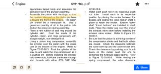
Side clearance between piston ring and piston (514, 515, 516and517). Pistons forAvco Lycoming opposed engines are ground with a slight taper from the skirt to the head, with the exception of the lands between the top compression and oil control rings, which are ground parallel. The clearance on wedge type compression rings therefore, must be measured as shownin figure6-11 in order to obtain a true check of the side clearance.
Lyc docs only speak to orientation of dot or letters on the ring and assumes no QA flaw as discussed above. Pretty easy to look in the land area ans see where the corresponding bevel is. Also the ring wont go all the way in if you get it wrong.
Pretty sure the lyc pistons do not have an offset pin bore
Would be amazing if these two threads merged. Really sorry you encountered this issue to the OP.OP,
Given this post, I would go look at the bevel orientation. The pic you posted sure looked like the bevel was facing up. And if it was, this would force the ring to sit proud of the piston and put heavy pressure on the ring once installed. It would explain the problem, so worth investigating.
This assumes superior etched the word in the correct place. Not sure you can assume that here. go look at the pic you posted. it sure looks like the bevel is up instead of down.I’ll grab some more photos soon. The top face of the ring has the part number and has “TOP” written on it - so it’s pretty hard to install it upside down. The bevel can clearly be seen also
We compared this to the old pistons and rings which were all correct so it was pretty obvious to see the discrepancy.
Unfortunately still no response from Lycon after 2 days
")
lndwarrior
Well Known Member
Also want to thank the OP for this post. I really enjoy learning about aircraft engines and I'm finding this entire thread educational and fascinating.
Sorry this happened to you! I can't imagine how frustrating it much be to have been so diligent and then have the manufacturer screw something simple, yet incredibly important, up.
Sorry this happened to you! I can't imagine how frustrating it much be to have been so diligent and then have the manufacturer screw something simple, yet incredibly important, up.
sansoneservices
Well Known Member
W100 is fine, not the best choice for break-in but won't cause any damageThey’re new Superior cylinders, 4hrs runtime before the images above.
I’ve just discovered that I have been using the wrong oil: Aeroshell w100 which is an ashless dispersant oil, not a straight mineral oil such as Aeroshell 100 or 80. I’m pretty worried that I need to take the engine apart now, lest I make it even worse by running scuffed pistons.
Not sure if this has been mentioned yet: there is a cylinder made into a lamp in my "Airplane Room" that, at one time was on an engine in a C-170. We had been out flying around downtown Denver one night, after attending an EAA meeting. Amazing flight! The next day the pilot had two of his three children in the 170; his third was with me in the Cub. I took off first, he followed close behind but, as he flew past me, I noticed something streaming out of the cowling. I told him and he said he was turning back as things were getting kind of 'rough'  ... When I landed, he was at the runway intersection with oil streaming everywhere. There was a fist-sized hole in the case. No idea what had happened. Pieces of piston in the bottom of the case.
Several months later (I was actually with him!) when it suddenly dawned on him: he had put a 10 under piston in a standard cylinder. It had been over 300 hours after the top overhaul before the piston finally shook itself apart.......and not over downtown Denver...........
Maybe another thing to consider..............
... When I landed, he was at the runway intersection with oil streaming everywhere. There was a fist-sized hole in the case. No idea what had happened. Pieces of piston in the bottom of the case.Several months later (I was actually with him!) when it suddenly dawned on him: he had put a 10 under piston in a standard cylinder. It had been over 300 hours after the top overhaul before the piston finally shook itself apart.......and not over downtown Denver...........
Maybe another thing to consider..............
Last edited:
Unfortunately the news is not good. I took off another cylinder and out of curiosity opted to remove the #2 rod to inspect the bearing.

All the other parts I’ve inspected so far have excessive wear - even the rocker shafts and wrist pins are showing wear as if they have been finely ground and polished. I don’t know what could cause this in only 4 hours runtime.
Either this damage was caused by the metal in the oil from the cylinder problem, or the whole process was caused by some foreign debris going around the engine and causing this to occur and the cylinder damage is one result.
The crank seems ok but the case will need to be split. Time for a beer…
More than one I would suggest!Unfortunately the news is not good. Time for a beer…
I guess this probably shows that re-checking ring gaps in all cylinders before assembly is probably the best thing to do!Thanks, the engineer has now seen the photos and says it’s nothing to worry about on a new engine.
I did not check the ring gap, as this was done by LyCon. The 8130 says “rings were fit”
sansoneservices
Well Known Member
I use a slide hammer to first pull out the long case thru bolts. Then I use the same slide hammer to separate the case halves. No other fancy special tools required. I had to weld a thread adapter to mate the 5/8" slide hammer threads to the 1/2" thru bolts. If you don't have access to a slide hammer (Amazon) I will loan you mine
sansoneservices
Well Known Member
The keep running it crowd also suggested to continue inspecting the oil filter and continue bore scoping
rocketbob
Well Known Member
Exactly.The keep running it crowd also suggested to continue inspecting the oil filter and continue bore scoping
I always follow the practice of changing the oil after the first engine ground run.
A lot of times we confuse good luck with bad luck. You may be thinking how unlucky you are when in fact, you’re extremely lucky.Unfortunately the news is not good.
You recognized something wasn’t right with your engine and against advice to fly it, you followed your gut instinct. The result of that persistence was you found that your engine was likely headed for a catastrophic failure…. Very lucky. And you found that out, in your shop…very lucky.
rocketbob
Well Known Member
Nothing to see here that indicates a catastrophic failure was imminent.The result of that persistence was you found that your engine was likely headed for a catastrophic failure…. Very lucky. And you found that out, in your shop…very lucky.
Sheesh Bob, I was trying to make io390 feel a little better about this colossal pile of crap that’s been dumped in his lap. Besides that, after the money spent on this engine, it already is a catastrophic failure.Nothing to see here that indicates a catastrophic failure was imminent.
simpkinsona
Well Known Member
I think you guys miss placed a decimal somewhere. Ring gaps should be in the neighborhood of .030 inches not .003 inches. Thirty thousandths, not three thousandths.
Yes - and there is a smaller gap at the top of the cylinder due to the cylinder "choke". Pretty good video here, which seems to show the steps that were missed:I think you guys miss placed a decimal somewhere. Ring gaps should be in the neighborhood of .030 inches not .003 inches. Thirty thousandths, not three thousandths.
Nothing more to add @IO390 but commiseration.

We can’t jump to any conclusions yet. I’ve only checked ring gaps on one cylinder so far, which were correct. I know how to measure ring gaps.
Once I removed the second cylinder and connecting rod and saw the bearing damage, I went home to drown my sorrows. After I’ve removed all the cylinders and checked all the ring gaps I’ll report back.
Once I removed the second cylinder and connecting rod and saw the bearing damage, I went home to drown my sorrows. After I’ve removed all the cylinders and checked all the ring gaps I’ll report back.
mike_tailwind
Member
I have run into a similar problem with the engine on my plane. Millennium cylinders on an O-320.-B2B. My wear pattern looks like yours. Cylinder #4 was the worst. I received a warranty replacement cylinder from Superior yesterday. I built the engine myself and the ring gaps were correct. Side clearances are tight. The rings move freely but I would say .0015 clearance on the top ring. I have 113 hours on it, but saw signs of scuffing at 50hrs. I would like to know the root cause, and whether I should request replacements for the other cylinders?We can’t jump to any conclusions yet. I’ve only checked ring gaps on one cylinder so far, which were correct. I know how to measure ring gaps.
Once I removed the second cylinder and connecting rod and saw the bearing damage, I went home to drown my sorrows. After I’ve removed all the cylinders and checked all the ring gaps I’ll report back.
mike_tailwind
Member

Here is a picture.
That looks exactly like mine!!!View attachment 84560
Here is a picture.
How do your other cylinders look?
If yours was a B3B then that’s exactly the same cylinder that I have. Can you PM me the serial number of your cylinder please?
mike_tailwind
Member
I checked, they both use the same cylinderThat looks exactly like mine!!!
How do your other cylinders look?
If yours was a B3B then that’s exactly the same cylinder that I have. Can you PM me the serial number of your cylinder please?
SL32006W-A20P
Having now split the crankcase, the thrust faces of the crank and case are severely damaged to the point that I don’t believe them to be repairable. That might explain the massive quantity of non ferrous metal in the oil.
Does anyone have an O320 for sale? Please PM me if so.
Does anyone have an O320 for sale? Please PM me if so.
sansoneservices
Well Known Member
Wait.. maybe I'm mistaken but doesn't the crank thrust mate with the large nose bearing? The case and crank might be salvageable
It’s probably worth sending the crank out for inspection. I had one that I thought wasn’t repairable due to pretty severe scratches on a journal and fortunately there was enough material that they were able to grind it down to the next size and re nitride it. Depending on the damage, the same may be true of the case. One of the shops out there I think will install a steel thrust surface on the case, which they may be able to do to yours. Hopefully someone else can tell you which shop does that.
Not a fun situation you are in, but there is a bit of hope.
Not a fun situation you are in, but there is a bit of hope.
Notice all the wear on one side of the bearing shell? The rings are too tight in the bore. In addition to that scraping all the metal off your cyl wall, it is adding a whole bunch of extra stress / pressure on the rod bearing. You only see it on one side, as it only happens on the up stroke. The rod is offset for most of the travel. The bottom bearing shell should show all the wear on the opposite side - the down stroke. This is from severe friction between the rings and cylinder wall.Unfortunately the news is not good. I took off another cylinder and out of curiosity opted to remove the #2 rod to inspect the bearing.
View attachment 84519
All the other parts I’ve inspected so far have excessive wear - even the rocker shafts and wrist pins are showing wear as if they have been finely ground and polished. I don’t know what could cause this in only 4 hours runtime.
Either this damage was caused by the metal in the oil from the cylinder problem, or the whole process was caused by some foreign debris going around the engine and causing this to occur and the cylinder damage is one result.
The crank seems ok but the case will need to be split. Time for a beer…
Having now split the crankcase, the thrust faces of the crank and case are severely damaged to the point that I don’t believe them to be repairable. That might explain the massive quantity of non ferrous metal in the oil.
Does anyone have an O320 for sale? Please PM me if so.
Any thoughts on what caused all this? It’s a hell of a lot of damage for only 4 hours of running.
We checked ring gaps on all 4 cylinders and they were all within limits, 0.045-0.055 in the bottom of the bore and over 0.0075 at the top.
I bought a new set of Lyco cylinders before I discovered the bottom end damage, so I compared these to the superiors.
Interestingly, the superior cylinders have .005 more choke at the top of the bore than the Lyco cylinders but the bottom of the bore measures exactly the same. This seems like a lot but is it enough to be a problem?
Sadly Lycon have ignored me for a week, so I’m going to contact superior.
Sump screen was completely clean. Only got as far as using one filter, there was a fair amount of metal in it.Maybe I missed it,
Is there anything in the screen in the sump? What oil filter are you using?
How much metal is in it and the previous filters?
Thanks
Tim
Probably a dumb question, but what filter?Sump screen was completely clean. Only got as far as using one filter, there was a fair amount of metal in it.
