To wrap up some of the previous posts....
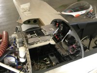
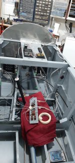
Static ports are done
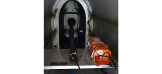
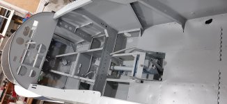
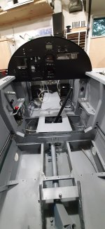
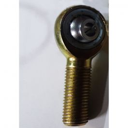
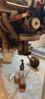
Rudder pedals are reinstalled (waiting on a few pieces of hardware )
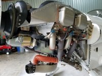
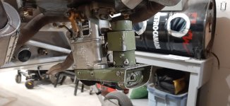
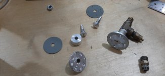
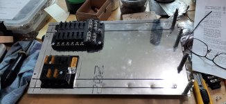
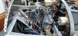
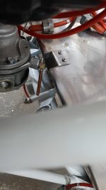
Master brake cylinder is plumbed on inlet side. I replaced the plastic plumbing fittings with some hydraulic fittings. When the shop made my lines up, they put those fittings on so I had to change over. I like them much better though. You can see them in one of the photos. Local shop so nice.
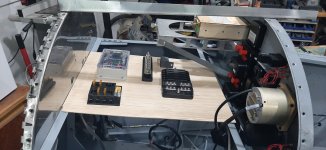
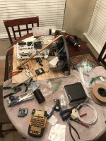
I assembled the FlyLED's control module for the Strobe/Nav lights. I will give them a kudos. Nice PC board to work with. Well documented kit. Good support.
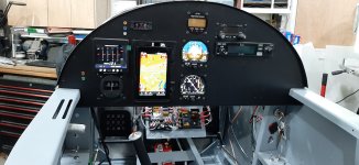
I decided to take the advice and sentiment expressed in previous posts and ditched the little rocker switches for more robust toggle switches. Thanks for the input there.
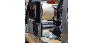
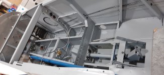
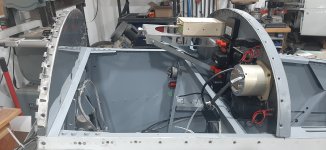
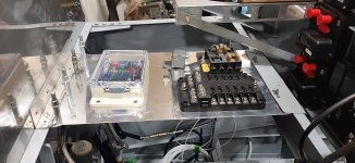
I am starting to work on the wiring. I will be putting a shelf behind the instrument panel to support the fuse blocks, grounding blocks, light control module, etc. I looked at options like on the floor for the control module, firewall for the fuse blocks, etc. but I like the shelf, and it be will be nice to install and for maintenance.
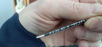
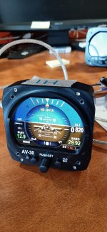
But, thinking about the wiring, how does one make the actual physical connections for the communications pins? I don't have much to connect, but the engine monitor can connect to the GPS RS232 lines to calculate fuel necessary, and the AV30's connect to the GPS for course information. The pins don't look large enough to put two wires into them. I think my system is too simple for the junction boxes I see in larger systems. So is it a matter of stripping the wire back from the pin and joining it there? I think Stein calls it
"window stripping"? That is about the best video that I have found but hoping someone can confirm this is what I need to do for the communications lines. Or do I use a terminal block outside of any connector? I would be concerned about losing shielding but maybe those lines are not sensitive to interference? Any suggestions?


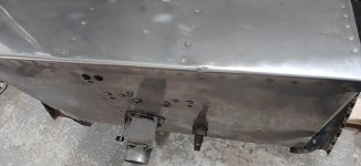
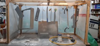
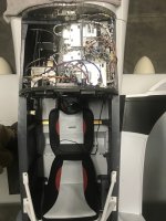
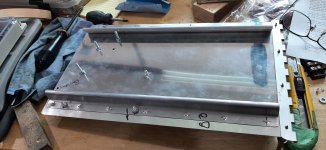
 Although not my favourite instrument layout now, the aluminum work turned out ok. And it was an interesting project. For anyone using an EDM350, the diameter of the case is actually around 3.000" so a regular instrument hole is sloppy. The mod allowed me to make the hole a better fit anyways.
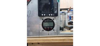

")


 Shawn
Shawn")


")