Yes, I messed it up despite reading the warning many times and measuring many times. Instead of 5/8 in, it came out to be 9/16 in. and I thought I could ignore it but I couldn't. I emailed Vans support and to my surprise, they responded "The dimension should be 5/8 from edge of the hole closest to the edge of the part" whereas the manual and every forum threads here stated distance from the center of the hole to the edge of the part. Maybe they had a senior moment, or I'm too dumb to build a plane, but anyways I decided to purchase the parts and drill out the rivets. I wonder if anyone here has successfully failed their first attempt then drill out and re-rivet the parts, and if they had any words of wisdom. I was able to drill out most of the -4 rivets without damage and seems like the best way to reach the bucking bar from the inside is to remove many rivets from the lower wing skin but I know there's someone smarter than me. Thanks!

Van's Air Force
You are using an out of date browser. It may not display this or other websites correctly.
You should upgrade or use an alternative browser.
You should upgrade or use an alternative browser.
Wing rear spar hole edge distance
- Thread starter yjchai
- Start date

I can't speak for your RV8, but on the 7 it's from the center of the hole. It's spelled out in a note on one of the drawings. And yeah, people have done what youre describing and been successful. Hopefully someone with that experience will see this and chime in.Yes, I messed it up despite reading the warning many times and measuring many times. Instead of 5/8 in, it came out to be 9/16 in. and I thought I could ignore it but I couldn't. I emailed Vans support and to my surprise, they responded "The dimension should be 5/8 from edge of the hole closest to the edge of the part" whereas the manual and every forum threads here stated distance from the center of the hole to the edge of the part. Maybe they had a senior moment, or I'm too dumb to build a plane, but anyways I decided to purchase the parts and drill out the rivets. I wonder if anyone here has successfully failed their first attempt then drill out and re-rivet the parts, and if they had any words of wisdom. I was able to drill out most of the -4 rivets without damage and seems like the best way to reach the bucking bar from the inside is to remove many rivets from the lower wing skin but I know there's someone smarter than me. Thanks!
Attachments
Send a picture with a scale or tape measure…
Hmmm
I don’t have one to measure but looking at pictures The spar stub from the fuse is at most 1.5” wide. The ideal center would be .75” from the edge. The edge of a 5/16” hole on that center would only be 0.594” from the edge. Already less than 5/8”. But they probably are more concerned about the wing spar flange.
I don’t have one to measure but looking at pictures The spar stub from the fuse is at most 1.5” wide. The ideal center would be .75” from the edge. The edge of a 5/16” hole on that center would only be 0.594” from the edge. Already less than 5/8”. But they probably are more concerned about the wing spar flange.
Last edited:
It should be center to edge. I doubt there's 5/8 from edge to edge.
Yes, happened to me. Mine missed by .009". They said live with it or replace parts. I actually came up with a pretty slick solution, but its for my 7A, Aft Spar.
Drill the aft spar carry through parts. Take your time. No need to rush. Slide them out.
Buy new parts.
Mark the new parts exactly where the two holes need to be. Maintain the width between the two holes, if possible. That's sweep. One end will be higher or lower. Next step fixes that.
Slide it back in.
Mount the wings.
On the 7, there is a little room to move the bar up, down and side to side.
Measure all that stuff. Get it as close as possible then clamp.
Drill a three or four of the rivet holes.
Take everything back apart.
Cleko and camp the old bar to the new bar and finish match drilling all the rivet holes.
Reassemble & rivet. Took me a month, but all the measurements landed exactly where they were before. Incidence, sweep, etc. She fly hands off.
If it makes you feel any better, I read where a second owner flew one for a year before noticing there were no bolts in the aft spar.
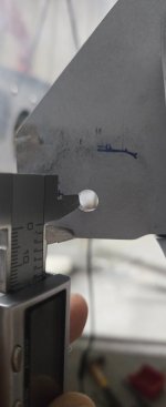
That's why I thought it was very odd for them to say otherwise, and I asked to confirm their instruction and they responded with generic information "you should effective have 2 diameters from the center of the hole in a part that is only drilled and not countersunk." Oh, ok. I'll replace it anyway. The caliper in the picture below is set to 5/8.
Attachments
Thanks for your tip! How did you reach inside to buck the rivets? Open up a bottom wing skin or reach in through a lightening hole?It should be center to edge. I doubt there's 5/8 from edge to edge.
Yes, happened to me. Mine missed by .009". They said live with it or replace parts. I actually came up with a pretty slick solution, but its for my 7A, Aft Spar.
Drill the aft spar carry through parts. Take your time. No need to rush. Slide them out.
Buy new parts.
Mark the new parts exactly where the two holes need to be. Maintain the width between the two holes, if possible. That's sweep. One end will be higher or lower. Next step fixes that.
Slide it back in.
Mount the wings.
On the 7, there is a little room to move the bar up, down and side to side.
Measure all that stuff. Get it as close as possible then clamp.
Drill a three or four of the rivet holes.
Take everything back apart.
Cleko and camp the old bar to the new bar and finish match drilling all the rivet holes.
Reassemble & rivet. Took me a month, but all the measurements landed exactly where they were before. Incidence, sweep, etc. She fly hands off.
If it makes you feel any better, I read where a second owner flew one for a year before noticing there were no bolts in the aft spar.
Sorry, mine was the aft spar. Wing spar would require a long arm, but I know it's been done. Maybe someone will post. It's possible the posts are still available via search.Thanks for your tip! How did you reach inside to buck the rivets? Open up a bottom wing skin or reach in through a lightening hole?
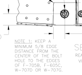
Take another look at the plans. Terry posted the Note above. 8 wings are the same as 7. I suggest calling back and asking for another tech and sharing a photo of your plans. I've had to correct once. Kinda sad.That's why I thought it was very odd for them to say otherwise, and I asked to confirm their instruction and they responded with generic information "you should effective have 2 diameters from the center of the hole in a part that is only drilled and not countersunk." Oh, ok. I'll replace it anyway. The caliper in the picture below is set to 5/8.
So, you're off by only 1/16 inch maybe, and most of the wing load is carried though the main spar. When the wing is pulling positive G's, the force is in the direction you actually have more edge margin. I really don't see a strong reason to rebuild that entire structure on both the wing and rear fuselage wing connect. There's not a compelling reason to rebuild the entire rear wing connect section, especially where the wing and fuselage rear connects have already been drilled though.Yes, I messed it up despite reading the warning many times and measuring many times. Instead of 5/8 in, it came out to be 9/16 in. and I thought I could ignore it but I couldn't. I emailed Vans support and to my surprise, they responded "The dimension should be 5/8 from edge of the hole closest to the edge of the part" whereas the manual and every forum threads here stated distance from the center of the hole to the edge of the part. Maybe they had a senior moment, or I'm too dumb to build a plane, but anyways I decided to purchase the parts and drill out the rivets. I wonder if anyone here has successfully failed their first attempt then drill out and re-rivet the parts, and if they had any words of wisdom. I was able to drill out most of the -4 rivets without damage and seems like the best way to reach the bucking bar from the inside is to remove many rivets from the lower wing skin but I know there's someone smarter than me. Thanks!
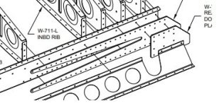
This is the area we are talking about right?

Last edited:
I understand that your concern is that you only have 9/16” instead of 5/8”…but just to clarify, Drawing 43 of the RV-8 plans (Section C-C attached) clearly shows that the 5/8” is from the edge to the center of the hole. I’m afraid that I don’t know the current generation of Vans tech Support folks like I knew the old gang (Ken, Joes, Gus, etc….), but I’d send them to that spot on the drawing and ask them to explain why they are interpreting it the way that they are. It coudl affect how you move forward with the replacements.

It's a 5/16 hole. Tech said 2D from the center. That's 5/8. Unless my math is wrong. Time to send them a wake up photo with scale and Paul's drawing above. Then file their response in your log. Imagine tearing that wing apart then finding out it's ok. Better to take a few days to get them on the same page.I understand that your concern is that you only have 9/16” instead of 5/8”…but just to clarify, Drawing 43 of the RV-8 plans (Section C-C attached) clearly shows that the 5/8” is from the edge to the center of the hole. I’m afraid that I don’t know the current generation of Vans tech Support folks like I knew the old gang (Ken, Joes, Gus, etc….), but I’d send them to that spot on the drawing and ask them to explain why they are interpreting it the way that they are. It coudl affect how you move forward with the replacements.
View attachment 108021
I've had several disappointing "advices" from Vans, and adding the questionable instruction regarding structurally important hole gives me less confidence in what they are recommending, so like any other paranoid builder would do, I will simply exercise the neverending practice of drill out and bang new ones in. I mean, 64 rivets can't be that bad, right?
I did spend several nights, thinking about that 1/16in less of aluminum won't cause the wing to fall apart in my first flight, but can I tell my passenger, whoever it may be, that I followed the instructions and you can entrust your life when I'm vertical doing hammerhead and gentle rolls...I guess it takes several dozen hours to fix the problem, but then I can say I cleaned up my mess. From prior posts, looks like other people have messed up and fixed them, I just didn't see their repair process and wanted some good old advice. I appreciate all of your replies!
I did spend several nights, thinking about that 1/16in less of aluminum won't cause the wing to fall apart in my first flight, but can I tell my passenger, whoever it may be, that I followed the instructions and you can entrust your life when I'm vertical doing hammerhead and gentle rolls...I guess it takes several dozen hours to fix the problem, but then I can say I cleaned up my mess. From prior posts, looks like other people have messed up and fixed them, I just didn't see their repair process and wanted some good old advice. I appreciate all of your replies!
You do realize that you would also need to replace the fuselage wing connect bar stock parts too -- not just the rear connect on the wing part because they are match drilled together, and once the wing angle of incidence is set properly (I assume you did that), you can't use that same hole location on the fuselage connect side either.I've had several disappointing "advices" from Vans, and adding the questionable instruction regarding structurally important hole gives me less confidence in what they are recommending, so like any other paranoid builder would do, I will simply exercise the neverending practice of drill out and bang new ones in. I mean, 64 rivets can't be that bad, right?
I did spend several nights, thinking about that 1/16in less of aluminum won't cause the wing to fall apart in my first flight, but can I tell my passenger, whoever it may be, that I followed the instructions and you can entrust your life when I'm vertical doing hammerhead and gentle rolls...I guess it takes several dozen hours to fix the problem, but then I can say I cleaned up my mess. From prior posts, looks like other people have messed up and fixed them, I just didn't see their repair process and wanted some good old advice. I appreciate all of your replies!
What is the actual distance from the center of your hole to the closest edge? Sure looks like 5/8 inch measured from hole center to edge is the correct answer for minimum distance -- same 5/8 inch shown on my RV-9A drawing, too!
")

Last edited:
The fuselage connect bar part has at least 5/8 to the edges, so my plan was to use it as my guide to drill it from both sides incrementally. I didn't think the fuselage part has to be replaced, but if enough experts chime in and convince me otherwise, I guess it will be done.You do realize that you would also need to replace the fuselage wing connect bar stock parts too -- not just the rear connect on the wing part because they are match drilled together, and once the wing angle of incidence is set properly (I assume you did that), you can't use that same hole location on the fuselage connect side either.
What is the actual distance from the center of your hole to the closest edge? Sure looks like 5/8 inch from hole center is the correct answer for minimum distance -- same 5/8 inch shown on my RV-9A drawing, too!
The actual distance on the wing side is 4.5/8 or 9/16, or I really want to round it up to 5/8. Based on the builders' consensus here, I'm glad to say I was right and I know how to read the instructions!
I’m not sure that a 1/16 variance is acceptable if you want to protect the planned structural integrity of the design. The design parameters are pretty clear. For a 5/16” hole, you need at least a 5/8” margin from the center of the 5/16 hole and the edge of the adjoining structural components. The structural components in this case is the clevis body (yoke), and the aft spar mount (the aft spar part that fits inside the yoke). Edge distance for these critical parts are clearly spelled out: 2D, from the attachment bolt hole center to the edge of any/all adjoining structural parts. Correcting mistakes made by misdrilling this critical hole may involve replacing the aft spar bars that make up the clevis and the wing aft spar structure that mates to it. I have first hand knowledge of this. Drilling out cabin floor rivets, and wing skin rivets to gain access to replacement of parts is more than half of the job, but not hard to do. Once everything is opened up, it’s not a huge job. Removing the misdrilled spar carry through parts and wing aft spar parts is relatively easy at this point, and installing the new parts is also. That critical aft spar bolt that holds your angle of incidence, and also carries a certain amount of the structural G limits of your aerobatic airplane needs to be carefully drilled. There are several people on this forum that have drill jigs that ensure edge distance clearance and accurate straight alignment for drilling that critical bolt. I’ve used a couple different ones myself, from stellar builders here - Jon Thocker, and Bruce Brielmaier. This made drilling that critical hole simple. That hole is one of the most serious functions you do in your build. There are also a couple on the tail that are almost equally important, but that’s not the point here.
Right -- the only way to get the wing "angle of incidence" correct is to replace the fuselage wing connect bars too, or you end-up with the same thing you have now or a wing with the wrong angle of incidence. I guess if you're looking at flying ring-out aerobatics, that 1/16 inch off might cause problems over the life of the airframe. But personally, I don't think it will based on how the wing actually carries G-loads.The fuselage connect bar part has at least 5/8 to the edges, so my plan was to use it as my guide to drill it from both sides incrementally. I didn't think the fuselage part has to be replaced, but if enough experts chime in and convince me otherwise, I guess it will be done.
The actual distance on the wing side is 4.5/8 or 9/16, or I really want to round it up to 5/8. Based on the builders' consensus here, I'm glad to say I was right and I know how to read the instructions!
But his photo shows he does NOT have 5/8 from edge to center, regardless of the bad guidance from Vans.It's a 5/16 hole. Tech said 2D from the center. That's 5/8. Unless my math is wrong. Time to send them a wake up photo with scale and Paul's drawing above. Then file their response in your log. Imagine tearing that wing apart then finding out it's ok. Better to take a few days to get them on the same page.
My plan was to replace the parts, unless Vans gave me a different repair instruction other than replacing the parts but then they said something completely unexpected. My intent for this post was to ask for advice on how to approach the repair most efficiently, not whether it needs to be done, but I enjoy the learning experience.
But his photo shows he does NOT have 5/8 from edge to center, regardless of the bad guidance from Vans.
Vans is pretty picky about the edge distance in that particular hole. I believe they had an incident where that part cracked in the past. You were definately not the first person to be told no exceptions from the 5/8" ED. I believe that is their official stance. The 5/8 from hole edge to part edge is just someone that made a mistake IMO. Unfortunate they were not willing to research the details and fix their error. Remember that you are the builder and don't need Vans permission to do anything. I would not follow their advice on the weird guidance you got untill it was verified by other sources at vans. Pretty sure there is not enough part material available to achieve it.My plan was to replace the parts, unless Vans gave me a different repair instruction other than replacing the parts but then they said something completely unexpected. My intent for this post was to ask for advice on how to approach the repair most efficiently, not whether it needs to be done, but I enjoy the learning experience.
Last edited:
My bad. I read he had 9/16 from edge of hole to edge of part. Add 5/32 for 1/2 the bolt hole=23/32. More than 5/8 if my math is right.But his photo shows he does NOT have 5/8 from edge to center, regardless of the bad guidance from Vans.
Yea, I do that all the time. Saw a few posts saying the same and didn't want the OP thinking it was OK.My bad. I read he had 9/16 from edge of hole to edge of part. Add 5/32 for 1/2 the bolt hole=23/32. More than 5/8 if my math is right.
My RV-9A drawing shows 3/4 inch spacing from center of bolt hole to the bottom edge of the rear wing connect stub, with a 5/8 inch minimum spacing. So, the optimum spacing (3/4 inch) to minimum spacing (5/8 inch) is actually 1/8 inch, which is substantial. Because the fuselage mounting bar stock can actually end-up overlapping after the wing angle-of-incidence adjustment is made, it's easy to get the edge margin less than 5/8 inch because the wing spar stub can become somewhat hidden during match-hole drilling process. My photo below shows this -- so, marking the actual wing stub line with a Sharpie on the rear mounting bar is probably a good idea -- that's what I did.

Last edited:
dnimigon
Well Known Member
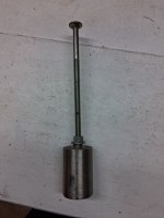
How are you using this ???This is what I made to buck the rivets
I did not remove bottom skin to buck the rivets on my redo. This area of rear spar has several(4) ribs a few inches apart. I was unable to reach between the ribs to buck. So I made this bucking bar extension to reach from a lightening hole to the rear spar. My wing was in a cradle leading edge down so I was reaching up with this bucking bar to buck on the front of the rear spar. Take your time. Its a tedious task but can be done
Thank you everybody, especially for the idea of reaching in with an elongated custom bucking bar without removing the wing skin. I wonder if using an 12 in back rivet set can achieve something similiar, just in opposite direction. I don't have it so will be a nice collection to my tools.
Which part was less than 5/8”? Also, the edge distance is measured from the center of the hole. Check that with Van’s again. I get a feeling this is a communication problem not a knowledge problem. Stop drilling anything more out until you have formulated a plan based on knowledge confirmed to be true.Yes, I messed it up despite reading the warning many times and measuring many times. Instead of 5/8 in, it came out to be 9/16 in. and I thought I could ignore it but I couldn't. I emailed Vans support and to my surprise, they responded "The dimension should be 5/8 from edge of the hole closest to the edge of the part" whereas the manual and every forum threads here stated distance from the center of the hole to the edge of the part. Maybe they had a senior moment, or I'm too dumb to build a plane, but anyways I decided to purchase the parts and drill out the rivets. I wonder if anyone here has successfully failed their first attempt then drill out and re-rivet the parts, and if they had any words of wisdom. I was able to drill out most of the -4 rivets without damage and seems like the best way to reach the bucking bar from the inside is to remove many rivets from the lower wing skin but I know there's someone smarter than me. Thanks!
In the future (and there will be more problems in the future), ask before you start drilling. I repeated this for emphasis. Good luck.
Not a rule of thumb here. This is what was designed with whatever safety margin the original engineers used.I am having a hard time believing that missing the rule of thumb 2d edge distance by 10 percent justifies doing that rework
Maybe it’s a wide margin and 10% is just dipping into a little, or, maybe not.
Vans also provides guidance about reworking rivets and that likely the reworked joint will weaker. Those are big long rivets in a stack that to me are challenging to remove. Then you have to match drill a new part with a pre punched holes to the existing holes that can easily be oversized removing the rivets. I would say it is worth some more communication with an engineer.Not a rule of thumb here. This is what was designed with whatever safety margin the original engineers used.
Maybe it’s a wide margin and 10% is just dipping into a little, or, maybe not.
Last edited:
My instructions said edge distance on this part is one of few in the whole build that is absolute


My understanding as well. I believe there was one that let go in the past and the cause was to little meat in that area. This seems like one area vans says nothing other than sorry, it needs to be redone. This is a key, high load structural area. Were not talking about a rivet hole that was overdrilled on a skin here. We are talking about a key, high load structural area Some areas have margin for mistakes and some don’t. I am not one of those guys that drills out rivets because they don’t look perfect. When i found an ED violation in this area on the kit that i bought, I spent days removing the spar plate from the wing. My arm looked like it got stuck in a garbage disposal. Not a fun job. But this is Not an area to say thats good enough in my opinion.My instructions said edge distance on this part is one of few in the whole build that is absolute
Last edited:
“Extremely important” is not a phrase used too much in the manual, please take that as a clue that this is not an area to say, “awe, what can it hurt? Lot of material still there”It kinda does. But, I would still talk to Vans support about it being from hole center to edge -- not hole edge to edge of part as they told you.
View attachment 108168
I seem to recall that Van’s approved an alternate fix which involved a doubler. But I don't recall specifics
Because you will lose the hardening in the metal and create excessively hard, brittle metal near the weld (HAZ). Designers account for this when specifying welds in a design. No such specification here, so quite dangerous.Surely there has to be a better fix than drilling out all those rivets?
Welding is not my thing, but why can’t you weld up the hole and try again?
I agree with you and to repeat, my question is not whether I should replace the parts but how. Can you share your method and how you approached the removal and riveting of the parts with minimal damage to the skin and other parts?My understanding as well. I believe there was one that let go in the past and the cause was to little meat in that area. This seems like one area vans says nothing other than sorry, it needs to be redone. This is a key, high load structural area. Were not talking about a rivet hole that was overdrilled on a skin here. We are talking about a key, high load structural area Some areas have margin for mistakes and some don’t. I am not one of those guys that drills out rivets because they don’t look perfect. When i found an ED violation in this area on the kit that i bought, I spent days removing the spar plate from the wing. My arm looked like it got stuck in a garbage disposal. Not a fun job. But this is Not an area to say thats good enough in my opinion.
Wing Incidence Drilling - Van's Aircraft Total Performance RV Kit Planes
DRILLING THE WING — SIMPLIFIED Don’t put in all of the wing attach bolts right away! You may have to remove each wing a couple of times in this process. Just put in four bolts in a square pattern for each wing. Don’t use the good bolts! Put in hardware store variety and grease them […] Read More
 www.vansaircraft.com
For future RV8 builders there is a trap you can fall in this area. Most builders find that when they set the wing incidence as per the plans the flaps end up lower than the fuselage. If you try to get them to align by moving the wing up you run the chance of busting that edge distance.
I think you are replacing the structure in the fuse. Please confirm. In my case that part was ok. The ED was blown on the wing based part. I went in via the lightning holes in the ribs. If that is what you are doing, I can provide some more insight.I agree with you and to repeat, my question is not whether I should replace the parts but how. Can you share your method and how you approached the removal and riveting of the parts with minimal damage to the skin and other parts?
I think you are replacing the structure in the fuse. Please confirm. In my case that part was ok. The ED was blown on the wing based part. I went in via the lightning holes in the ribs. If that is what you are doing, I can provide some more insight.
I'm replacing the wing based parts.
I hesitate to chime in but this may be helpful to the OP or others contemplating this challenge. I was faced with a similar dilemma on the rear spar attach fitting on my RV-4. In my case I had in irregular hole (edge of one side having a deformity) with the center having the 2 x diameter edge distance. I made the decision, a rash one as it turned out, to clean up the hole by enlarging it to .375" with a steel boring jig so I only removed material from the deformed edge of the hole. This left me with the min. called out .625" center of hole edge distance but with the 2x diameter of a 3/8" bolt it would have calculated to .750". I flew the 4 like this for several years and had even pulled 6 G's at one point but I always had that nagging doubt in the back of my mind.
During a refresh and extensive upgrade of my 4 at the 1000 hr milestone I became determined to get a definitive answer to what the actual strength of my attach fitting was in comparison to the per plans design thinking I might put a limit on my airframe of 4 or 5 G's instead of the Acro weight limit of 6G's. I consulted with a highly qualified engineer who I found here on VAF who had done work for Van's and he graciously agreed to run a structural analysis on my attach fitting .
In summary he determined: " That the larger bolt attachment is actually somewhat stronger due to the greater bearing surface area resisting shear tear-out." The per plans design ultimate-load safety factor calculated to 1.25 while my botched joint calculated to a 1.5 safety factor. This was a pleasant surprise to say the least.
I have the full analysis with calculations in my build book along with a summary card with signature in my airframe condition inspection record book. In my specific case I was left with .4375" edge of hole to edge of material and with a 3/8" bolt hole and that was stronger than the .4687" edge of hole distance with a 5/16" bolt hole.
Could the OP resolve his building error in the same way ? Thats a very personal decision he'll have to make. As for me If I was still in the building phase I would probably start drilling rivets.
I drilled all the heads from the back. Then partially drilled center of rivets 3/32 to soften them up. Then you need to make a tool to go over the shop head on the back side so that when you hit the punch to drive the rivet out it doesn't bend the rib flanges. Then buy a chunk of aluminum the correct size and match drill from the old part. I was able to get a bucking bar on pretty much every rivet by going through the rib holes, but hacked my arm up pretty good doing so. I need a 3 or 4 cherrymax rivets where I couldn't get a bucking bar in there. I never even considered pulling skins to do this, so can't say if that approach is better or worse.I'm replacing the wing based parts
Last edited:
Okay -- then, by using that same hole that was drilled in the fuselage bar stock mount, this would mean that the wing angle-of-incidence would have to be increased by needing to drop the wing mounting stub down further to meet the 5/8 inch minimum ED -- right? I understand that the wing angle-of-incidence isn't as critical as the other wing mounting measurements as long as the wing angle-of-incidence is the same on both wings. But, how much additional angle-of-incidence are you actually allowed? And, wouldn't the forward wing connect also need to be redone if it were already drilled?I think you are replacing the structure in the fuse. Please confirm. In my case that part was ok. The ED was blown on the wing based part. I went in via the lightning holes in the ribs. If that is what you are doing, I can provide some more insight.
Question 2 -- has the other wing rear mounting hole already been drilled?
Question 3 -- how much wing alignment and mounting work has already been done?
Last edited:
Thanks for this. The 2D edge distance becomes nonsense at some point especially with a double shear connection . I think a possible engineering approved fix would be to upsize the bolt to 3/8 and leave it alone.I hesitate to chime in but this may be helpful to the OP or others contemplating this challenge. I was faced with a similar dilemma on the rear spar attach fitting on my RV-4. In my case I had in irregular hole (edge of one side having a deformity) with the center having the 2 x diameter edge distance. I made the decision, a rash one as it turned out, to clean up the hole by enlarging it to .375" with a steel boring jig so I only removed material from the deformed edge of the hole. This left me with the min. called out .625" center of hole edge distance but with the 2x diameter of a 3/8" bolt it would have calculated to .750". I flew the 4 like this for several years and had even pulled 6 G's at one point but I always had that nagging doubt in the back of my mind.
During a refresh and extensive upgrade of my 4 at the 1000 hr milestone I became determined to get a definitive answer to what the actual strength of my attach fitting was in comparison to the per plans design thinking I might put a limit on my airframe of 4 or 5 G's instead of the Acro weight limit of 6G's. I consulted with a highly qualified engineer who I found here on VAF who had done work for Van's and he graciously agreed to run a structural analysis on my attach fitting .
In summary he determined: " That the larger bolt attachment is actually somewhat stronger due to the greater bearing surface area resisting shear tear-out." The per plans design ultimate-load safety factor calculated to 1.25 while my botched joint calculated to a 1.5 safety factor. This was a pleasant surprise to say the least.
I have the full analysis with calculations in my build book along with a summary card with signature in my airframe condition inspection record book. In my specific case I was left with .4375" edge of hole to edge of material and with a 3/8" bolt hole and that was stronger than the .4687" edge of hole distance with a 5/16" bolt hole.
Could the OP resolve his building error in the same way ? Thats a very personal decision he'll have to make. As for me If I was still in the building phase I would probably start drilling rivets.
Thank you for sharing your approach.I drilled all the heads from the back. Then partially drilled center of rivets 3/32 to soften them up. Then you need to make a tool to go over the shop head on the back side so that when you hit the punch to drive the rivet out it doesn't bend the rib flanges. Then buy a chunk of aluminum the correct size and match drill from the old part. I was able to get a bucking bar on pretty much every rivet by going through the rib holes, but hacked my arm up pretty good doing so. I need a 3 or 4 cherrymax rivets where I couldn't get a bucking bar in there. I never even considered pulling skins to do this, so can't say if that approach is better or worse.
As to other questions, I will have to figure out as I go. Fuel tank attachment bracket can be remade and redrilled so I don't think that will be a big challenge. As to wing incidence, maybe I'll be lucky to be within spec not to rework the fuselage part. Maybe the wing moved as I was drilling the hole in increments but the initial measurement was fine, or the initial measurement was wrong to begin with.
