Van's Air Force

The definitive Van's Aircraft support community! Buying, building or flying an RV? Join our exclusive family of mentors and enthusiasts!

Small RV-10 Elevator Skin Wrinkles - symmetrical on both elevators

rvmills

Well Known Member
Friend
Placed this in General for wider exposure. Although this was found on an RV-10, perhaps this has been seen on other 10's and other RVs as well.

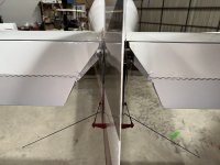
While assisting a friend on his RV-10 Condition Inspection, the following wrinkles were noted on the inboard, upper elevator skins. There do not appear to be cracks in the skin, but the flex in the skin has caused the paint crack away. We'll be sanding some paint away to inspect further. His call to Van's yielded a "not something to be concerned about" reply, but we're not sure the pictures he sent in shared the issue well enough (he sent closer up photos than what I'm posting, which showed the interior, by the rear elevator spar, the elevator root rib, and trim tab "spar" all appearing normal...no odd wear, and looks to be built per plans...owner was not the builder).

Please see further discussion below photos, with possible hypothesis, and request for any feedback...or any experience with the same phenomenon.

IMG_6246.JPG

IMG_6243.JPG

IMG_6244.JPG

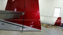
In the next photo, the dotted red line represents the front face/web of the elevator rear spar, and the solid blue line represents the small gap between the front face of that spar web, and the aft edge of the elevator root rib. There is no metal that ties those last two rivets together, other than the skin itself. The root rib is under the rivets forward of the blue line, and the rear spar flange is under the last rivet on the elevator skin. That appears to be in sync with the plans, so that is not an arrow fired at the design. It is very interesting that the small creases are very symmetrical. The owner has hypothesized that the aerodynamic forces on the elevator and the trim tab may be acting to alternatively stretch, then compress the elevator skin...somewhat along the axis of the double-sided red arrows. I watched the skin and the creases carefully as he actuated full up and down trim, and saw no flexing. I tried to simulate aero loads on the tab and the elevator with my hands, and saw no flex. We bounced around the idea of adding a thin doubler to span that gap between the last two rivets, but that will make the skin uneven, or may create unintended structural consequences. We're also hesitant to work the area back to flat, for fear of work-hardening, and likely follow-on cracking.

Any other experience with this in the field? Thanks!

Cheers,
Bob


IMG_6243.JPG
 

Attachments

  • IMG_6246.JPG
    IMG_6246.JPG
    111.4 KB · Views: 83
Perhaps rope marks from using a rudder locking device like this, but running over the top of the elevator instead of under it like in the photo.
Carl
 

Attachments

  • IMG_0516.jpeg
    IMG_0516.jpeg
    2.3 MB · Views: 108
Perhaps rope marks from using a rudder locking device like this, but running over the top of the elevator instead of under it like in the photo.
Carl
Thanks Carl...I'll ask about rudder locks. There is however, a slight transverse wrinkle upwards in the top of the skin. It's barely visible in the photo below...just below, almost touching, the red dotted line. You can kind of make it out by the slight difference in shadowing. It doesn't appear to be a physical wear/rub mark.

IMG_6243.JPG

Cheers,
Bob
 
I’ve seen this on a 14 as well. I’m assuming it to be an mis match in height of the rear spar & rear side rib.
Does your pictures show the paint flexing off in those areas too? That would be very worrisome.
 
I’ve seen this on a 14 as well. I’m assuming it to be an mis match in height of the rear spar & rear side rib.
Does your pictures show the paint flexing off in those areas too? That would be very worrisome.
Thanks Ralph! The only paint or skin flex we see is those in the photos. Brian Decker is going to swing by and help us scope the tail tomorrow :)

Cheers,
Bob
 
Thanks Ralph! The only paint or skin flex we see is those in the photos. Brian Decker is going to swing by and help us scope the tail tomorrow :)

Cheers,
Bob
Any chance the aircraft has been over-speeded with the trim full nose-up ( and possibly flaps down)?
 
I saw something similar happen due to hangar rash once - guy backed an airplane into the back of the hangar, tagged both elevators and wrinkled the HS just forward of the hinges, even though you had to look hard to see any paint damage on the elevators themselves.
 
Any chance the aircraft has been over-speeded with the trim full nose-up ( and possibly flaps down)?
I don't think so...he's a careful pilot and a good stick...and he'd own it if he'd oversped it. His description of the trim change from landing speed and attitude to cruise speed and attitude is that it is a significant, but otherwise normal, amount of trim. That's part of what led him to the hypothesis that trim cycling in normal ops is leading to this.

Cheers,
Bob
 
I saw something similar happen due to hangar rash once - guy backed an airplane into the back of the hangar, tagged both elevators and wrinkled the HS just forward of the hinges, even though you had to look hard to see any paint damage on the elevators themselves.
I looked at the trailing edges carefully for evidence, and there is none. The wrinkles are uncannily symmetrical too...it would have been a one in a (many) shot to do that.

Brian D has some other suggestions for looking to ensure the structure was put together completely to plans, and some ideas on a fix, even it it was. Still a bit of a mystery. ;)

Cheers,
Bob
 
I fly an RV9 and I have a microcrack a bit lower at the trim hinge rivet. It's been closely watched for a number of years and it's not propagating. Now that Kyle said it I would guess the possible reason.
 
I looked at the trailing edges carefully for evidence, and there is none. The wrinkles are uncannily symmetrical too...it would have been a one in a (many) shot to do that.

The rudder TE is a fair way behind the elevator TEs too.

Be interesting to hear what the factory thinks?
 
This was my thought - 10's typical have a stick lock which would have to transfer a parked gust load into that end rib. Right where the mark shows.
A gust load from what though? The trim tab? That’s a pretty flimsy part compared to the rear spar of the elevator.
That joint between the rear spar, rib and skin is completely constrained with no scope for movement.

If I had to speculate here I’d say the rib flanges were not seamed to 90 deg during construction leaving a kink in the skin when it was riveted (the giveaway is the kink perpendicular to the skin edge - coincident with the underlying rear end of the rib flange)
It appears to me also from the pictures above that the paint has actually worn of rather than debonded due to movement. There also seems to be evidence of scuffing or wear.
I’d say that perhaps the previous owner or someone has had a rudder lock mechanism or rope that has worn the paint off. It could easily have happened over just one night with an inappropriate lock.
 
What does the underside look like? If the rib was too tall for the rear spar, and the riveting pulled it down forming a crease, there would probably be one on the bottom too. This looks to me like a single-event overload, not a cyclic loading problem. High trim loads from exceeding max flap speed with flaps down, or a semi-aerobatic event, or a very strong gust, or? I'm surprised that there is no tab on the back of the elevator root rib that would get riveted to the rear spar - especially since they went to the trouble to design the shear clips for the other internal stiffeners. A vertical load with only the skin holding those parts together would do just what you see.
 
A gust load from what though? The trim tab? That’s a pretty flimsy part compared to the rear spar of the elevator.
That joint between the rear spar, rib and skin is completely constrained with no scope for movement.

If I had to speculate here I’d say the rib flanges were not seamed to 90 deg during construction leaving a kink in the skin when it was riveted (the giveaway is the kink perpendicular to the skin edge - coincident with the underlying rear end of the rib flange)
It appears to me also from the pictures above that the paint has actually worn of rather than debonded due to movement. There also seems to be evidence of scuffing or wear.
I’d say that perhaps the previous owner or someone has had a rudder lock mechanism or rope that has worn the paint off. It could easily have happened over just one night with an inappropriate lock.
If the gust lock is simply holding the stick, as many 10s do, then it may depend on where it is held. It could even have been slammed against the stop, or a strong tail wind gust would generate a torque from wind load on the entire elevator. That inboard rib is what carries that torque into the pivot structure. If the elevator is as held statically the torque could be substantial, especially if there was some slack ( or no gust lock) and it was slapped by a gust. Vans could calculate how much and what it would take to twist the elevator enough to crease the skin and crack off the paint. They could also (knowing the forces) determine if other parts between the elevator and stick should be inspected for damage.
 
Yes I can see how the rear spar could twist and manifest at the inboard end, but I also think that would be obvious on the bottom side as well.
It would probably also be apparent at the outboard end of the trim tab because the stiffener tie ins to the rear spar are much lighter than the inboard rib.

I certainly agree that if you can’t rule out it being a cosmetic wearing of the paint then the aircraft should be grounded because the forces required to do that would be significant.
I’d actually think it more likely from a gust slamming the unrestrained elevator against the stop.
 
I'm surprised that there is no tab on the back of the elevator root rib that would get riveted to the rear spar ....
If that is so, it would seem to contradict Bob's observation:
"...and the solid blue line represents the small gap between the front face of that spar web, and the aft edge of the elevator root rib. There is no metal that ties those last two rivets together, other than the skin itself."

If there is supposed to be a tab on the rib that connects it to the spar, and it is missing, that would allow the vertical shearing of one relative to the other.

I guess I should have said “there should be” :-) I must have subconsciously missed that and just assumed it was built to plans.
Not only should there be a tab on the rib, there also should be a shear clip (which is 063 of so - beefy) on the inside.
Hence my comment about that joint being very strong.

I guess anything’s possible. I’d be very surprised if the build was equally non compliant on both sides.
All bets are off in that case.

IMG_2933.jpegIMG_6333.jpeg
 
Last edited:
I guess I should have said “there should be” :-) I must have subconsciously missed that and just assumed it was built to plans.
Not only should there be a tab on the rib, there also should be a shear clip (which is 063 of so - beefy) on the inside.
Hence my comment about that joint being very strong.

I guess anything’s possible. If it’s missing those I’d be horrified that someone would think that’s a sensible omission.
All bets are off in that case. Could have bent in the flare. I’d be a very anxious owner in that case.

View attachment 74476View attachment 74477
Thank you for taking the effort to show this. I think it will help Bob enormously with understanding what is going on there.
 
I guess I should have said “there should be” :-) I must have subconsciously missed that and just assumed it was built to plans.
Not only should there be a tab on the rib, there also should be a shear clip (which is 063 of so - beefy) on the inside.
Hence my comment about that joint being very strong.

I guess anything’s possible. I’d be very surprised if the build was equally non compliant on both sides.
All bets are off in that case.

View attachment 74476View attachment 74477

Thank you for taking the effort to show this. I think it will help Bob enormously with understanding what is going on there.

Richard, as Steve said, thanks for the detail and photo you provided...very helpful. Steve, thanks for the heads-up text on this.

Brian Decker sent us the same plan detail, and suggested a similar look into the interior. His thought was that, if all the components are installed...and installed correctly...that it could be oil canning in that area. The symmetry of the wrinkles and marks is somewhat uncanny though (perhaps a teensy bit of a pun Brian), so any install error would have to be bilateral, and very similar (not out of the question). I've asked if I can pull those trim actuator covers and peek inside. I'll see what I can see.

Here's a marked-up copy of what Richard sent, to show where the trim tab would be (red...and of course, it goes further to the right), where the gap is that I marked earlier (large blue line...the small blue line would be the tab hinge line), as well as the wrinkle/paint crack that we are seeing (gray):

Screenshot 2024-11-17 at 5.54.06 AM.jpeg

Really appreciate all the posts from various folks...thank you! A bit of feedback on some of them, as we continue to investigate:

- He has a stick-type gust lock...sounds fairly typical for 10s, so we discussed a gust load while the lock was on. It's possible...he's been to OSH often, and has endured some of those wind events. He has not used any strap or other tail surface gust lock, so mechanical wearing does not appear to be a player here.

- Overloading/overspeeding with flaps extended...he does takeoff with partial flaps, and his plane climbs really well. He doesn't believe he has oversped the flaps by much, if any, during normal ops.

- I don't see any marks on the bottom skin, but I'm going to take a closer look.

Will take some photos of the inside and outside of the root rib-to-spar web connection, as well as the inside of that upper skin (if I can get a good photo in there).

Thanks again all!

Cheers,
Bob
 
Last edited:
- Overloading/overspeeding with flaps extended...he does takeoff with partial flaps, and his plane climbs really well. He doesn't believe he has oversped the flaps by much, if any, during normal ops.
If by partial flaps you meant ‘in trail’, Vans removed all speed restrictions some time ago.
 
The location and orientation of the cracks in the paint is conducive to what would be expected from a longitudinal compression load on the skin in that area with the largest deflection of the skin centered between the two rivets.
The elevator trim tab in the full up elevator trim position (deflected full down, as it might be during landing) will apply this type of load to the aft spar and upper skin.
If the internal corner clips are not installed, I could easily believe that the resulting deflection could be enough to crack some paint finishes and possibly even some permanent deformation might occur.
I don’t remember for certain, but I have a faint memory of the clips being added based on results of static load tests on the elevator and trim tab.
It will be interesting to hear what you find Bob.
 
Last edited:
The location and orientation of the cracks in the paint is conducive to what would be expected from a longitudinal compression load on the skin in that area with the largest deflection of the skin centered between the two rivets.
The elevator trim tab in the full up elevator trim position (deflected full down, as it might be during landing) will apply this type of load to the aft spar and upper skin.
If the internal corner clips are not installed, I could easily believe that the resulting deflection could be enough to crack some paint finishes and possibly even some permanent deformation might occur.
I don’t remember for certain, but I have a faint memory of the clips being added based on results of static load tests on the elevator and trim tab.
It will be interesting to hear what you find Bob.

Here are some photos, from both inside the elevator (the clips are indeed installed), and from outside, showing the opposite side of some of the rivets.

IMG_8795.JPG

IMG_8796.JPG

IMG_8797.JPG

IMG_8798.JPG

IMG_8778.JPG

IMG_8779.JPG

IMG_8773.JPG

The installation looks to be per plans, though a couple rivets may be slightly over-squeezed. The owner received an e-mail from Vans (not sure from whom, but he had looked at the last couple photos from outside), that said those rivets looked oversized to him. The shop heads don't appear so (to me), and it doesn't appear to encroach on proper edge distance on the outside...so not sure if that is a factor here. There do not appear to be any cracks radiating from any of the rivets.

The outside photos appear to show that the deformation is in the area of the aft elevator spar web (noted by the red arrows).

Scott, your comment about the trim tab flexing the spar upwards when fully deflected may have some merit, though the clips are in. We ran the trim full nose up, but I saw no such deflection, and I tried to simulate some load on the tab too. Might be different with true aero loads on the structure.

The gap between the hinge and the spar cap (flange) and the v-shaped gap between the skin and the spar cap are interesting.

Not sure what assessment to make at this point. Thoughts?

Cheers,
Bob
 
Dumb question from a non-engineer farmer who has used bailing wire.... Could the hinge pin be tied tight enough to the spar to be pulling the end of the hinge "in towards the spar" resulting in a deformation stress buckle? Wonder what that area would look like if the safety tie was cut and removed...FWIW which may be not much.
 
The owner received an e-mail from Vans (not sure from whom, but he had looked at the last couple photos from outside), that said those rivets looked oversized to him. The shop heads don't appear so (to me), and it doesn't appear to encroach on proper edge distance on the outside...so not sure if that is a factor here.

Bob, that was the first thing that jumped out at me as well - maybe just a trick of the camera perspective, but those universal-head rivets look positively huge, like AD5 size. Though as you said, it doesn't look specifically wrong or unsafe - just unusual.
 
Looks to me as though it was built with some pre-compression in the skin, but maybe didn't buckle until later.

A possible way this could happen would be if the gussets were rotated 180 degrees between match drilling and riveting.
 
Here are some photos, from both inside the elevator (the clips are indeed installed), and from outside, showing the opposite side of some of the rivets.

View attachment 74749

View attachment 74750

View attachment 74751

View attachment 74752

View attachment 74753

View attachment 74754

View attachment 74755

The installation looks to be per plans, though a couple rivets may be slightly over-squeezed. The owner received an e-mail from Vans (not sure from whom, but he had looked at the last couple photos from outside), that said those rivets looked oversized to him. The shop heads don't appear so (to me), and it doesn't appear to encroach on proper edge distance on the outside...so not sure if that is a factor here. There do not appear to be any cracks radiating from any of the rivets.

The outside photos appear to show that the deformation is in the area of the aft elevator spar web (noted by the red arrows).

Scott, your comment about the trim tab flexing the spar upwards when fully deflected may have some merit, though the clips are in. We ran the trim full nose up, but I saw no such deflection, and I tried to simulate some load on the tab too. Might be different with true aero loads on the structure.

The gap between the hinge and the spar cap (flange) and the v-shaped gap between the skin and the spar cap are interesting.

Not sure what assessment to make at this point. Thoughts?

Cheers,
Bob
Good photos, Bob.
I wasn’t expecting the clips to be missing because with the pre-punch parts it would be a pretty glaring miss to do assembly and just leave open/un riveted holes, but I was somewhat hoping so that you would have a simple smoking gun answer.
I agree that some of the rivets appear oversized. I don’t know if that is just a function of how the photos were taken or what.
Depending on the tools a builder has, some of these rivets can be a bit challenging, so perhaps some were removed for replacement and in the process holes were messed up bad enough to require a bigger rivet diameter. In the process, the positioning registration of the rib in relation to the rear spar could have been lost, though the aft flange on the rib should have still maintained that.
It may be another factor somehow induced by the , but it seems as though the web of the rear spar may have some curve to it versus being flat. I can’t tell for certain because the end of the trim tab hinge wire is mostly blocking it from view. If it does, that could be another indication of something strange going on structurally in this area.
Definitely an interesting case.
I presume the current owner knows for certain that there was no bulge in the skin at that location when he purchased the airplane?
With a little bit of oil canning action, coupled with vibration, it could be possible for the paint to look fine for quite a while, but still have something abnormal with the skin profile.

The only other thing that comes to mind at the moment, and this is based on some of the crazy stuff I have seen over the years, is that this occurred from an excessive load from someone pushing on it such as helping to move the airplane while on the ground.
I realize it looks very symmetrical, but if someone were to straddle the rudder and push on the inboard end of both trim tabs while the elevators were deflected full up, I believe it would apply a compressive load into the skin that could have caused localized buckling of the skin in this location.
The fact that it is symmetrical could just be a function of someone pushing an equal amount with each arm.
 
Great replies guys...thanks very much. I'll talk with the owner about all the thoughts presented, and we'll explore them.

@docjjrmd, will play with that safety wire and see if things move

@mburch, agreed...the U-heads just look huge...but the shop heads look normal...though @Raiz, your comment about the flip after match drilling makes me wonder if they were upsized after doing something like that.

@rvbuilder2002, Scott, lot's of good thoughts...wondering if the skin may have been stretched a bit to put the clecos in at the aft spar and hinge...though in thinking that through, that would seem to pull the spar cap/flange and skin up, not press it down. Will look more closely at the aft spar web for a curve. Trying to think what might press the two aft spar flanges together to make that curve in the web happen (if it's indeed curved...will eyeball it today...hard to say from the pics). That actually does bring the thought of someone pressing down on both trim tabs together, but it's hard to imagine someone doing that...he's an experienced and careful operator, and would be watching. And to confirm...he just saw this for the first time on this condition inspection.

Still workin it! Thanks for the feedback all!

Cheers,
Bob

 
I just asked the question in the RV-14 forum but perhaps this issue is the reasoning for the change:

Revision 1 plans (6/27/23) on the RV-14 elevator have you install sealant all along the top and bottom corners of the rear spar where it meets the skins. Steps 7-9 which isn't in Revision 0.
 

Attachments

  • IMG_2372.jpeg
    IMG_2372.jpeg
    3 MB · Views: 9
I should have researched more before asking this question. It was quickly answered by another member:

"Van's has incorporated SB-00043 into the plans. It's supposed to prevent cracking of the rivet line on the -14 & -10."
 
I just asked the question in the RV-14 forum but perhaps this issue is the reasoning for the change:

Revision 1 plans (6/27/23) on the RV-14 elevator have you install sealant all along the top and bottom corners of the rear spar where it meets the skins. Steps 7-9 which isn't in Revision 0.
I should have researched more before asking this question. It was quickly answered by another member:

"Van's has incorporated SB-00043 into the plans. It's supposed to prevent cracking of the rivet line on the -14 & -10."
Thanks very much! I will pass this along to the 10 owner. Appreciate the time you took to research and report back!

Cheers,
Bob
 
Back
Top