If I simply temporarily cover a portion of the duct inlet with AL tape, would that validate the experiment? Why do you think that restricting the oil cooler flow won't help the No6 CHT?
The corrugated interior wall suggests a thick boundary layer, so true flow area is probably less than the nominal diameter, and it would get proportionally worse as the nominal diameter is reduced. A simple intake restriction wouldn't incorporate the effect of the duct walls, which is why I suggested inserting a length of actual 3" scat hose.
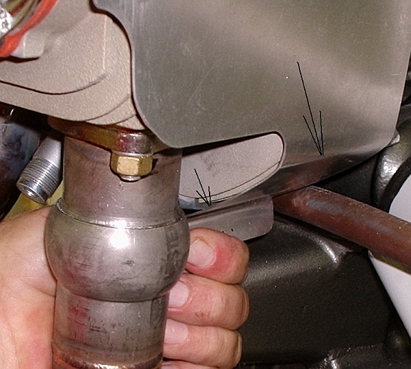
As to CHT, well, been there, done that. It started when measurement found a 16F to 17F difference between OAT and the face of the oil cooler, just down a short 4" duct from the #3 baffle wall. A little bit is compression heating, but most is heat picked up from the upper cylinder fins.
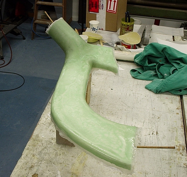
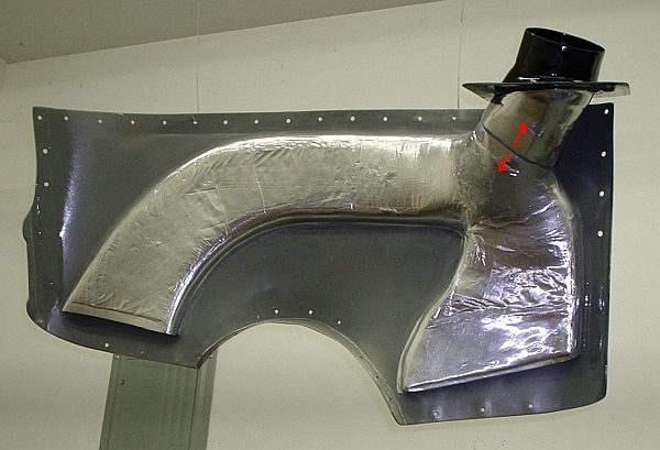
One way to lower oil temperature was to duct the oil cooler air supply all the way from the front of the plenum, just behind the cowl intakes, delivering lower temperature air to the oil cooler. It would also isolate cylinder #3, which would no longer have any of its cooling air supposedly "stolen" by the oil cooler duct inlet. So I built this insulated duct system.
Results: As expected, dropping delivered air temperature improved oil temperatures, even though I'm sure it reduced mass flow slightly (long flat ducts, not an optimum shape).
However, I noted no change to #3 CHT when I installed the above duct system, nor when I later removed it, returning to a flared intake hole in the rear baffle wall. A little thought tells why. The key factor driving air through the cylinder fins is simple pressure delta between the upper and lower cowl volumes. An oil cooler intake near the cylinder may flow a lot of mass, but if it does not reduce
pressure in the vicinity of that cylinder, the cylinder's cooling performance will not change. Setting aside frictional duct losses,
pressure should be pretty much the same in the oil cooler duct as it is in the upper cowl volume. It has to be. The upper/lower cowl pressure delta is what drives air through the cooler face, just like the cylinder fins. The pressure drop comes
after the cooler.
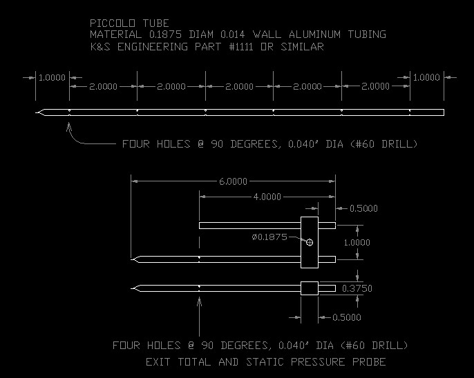
Admittedly, it's an observation and a theory. Confirmation or denial would be to install two piccolo tubes, one over each rear cylinder. One would be near the oil cooler inlet of course. Compare in-flight pressures. If the piccolo near the oil cooler duct inlet is lower by some significant amount, then (and only then) is the duct
stealing from the cylinder.
Finding +120F at 75% sounds like a good plan. Since the engine ran really sweetly at 2600RPM, I think I will run 2650 next year. If I can get the CHT down by 30F, then with a little leaner mixture I could possibly get 2-3kts extra. Over a near 2 hour race, that can make around 1:30m difference or 3:00m over the 2 days......
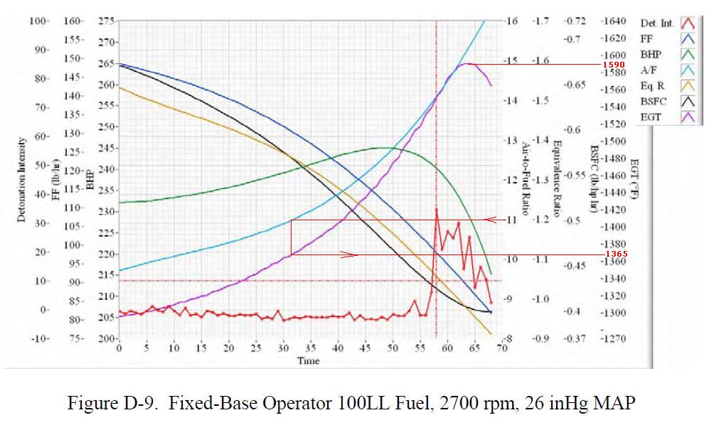
The mixture vs power curve is fairly flat in the ROP region, but there is a little power to gain with careful knob management. Here's an example, a 540K on the FAA dyno at Hughes, 26" and 2700, pretty close to what you mentioned as your race conditions:
Max power is about 245, at 125 ROP (1590 EGT vs 1465). Detonation onset is about 60 ROP, with full development around 50~45 ROP. The difference between heaven and **** is a spread of about 75F.
Remember, this data was taken when real hot, and the K is considered to be a worse case example. You might have a bit more leeway, or less, depending on compression and ignition advance.
First determine if you can run at best power mixture with the CHTs you have now. If so, work on CHT reduction. When you get it down by 30F or so, install a variable cowl exit to reduce mass flow at high airspeed. The restricted exit area will drive the CHTs back up to where you started, but you'll get the 2 knots.


 - work in progress.....