Van's Air Force

The definitive Van's Aircraft support community! Buying, building or flying an RV? Join our exclusive family of mentors and enthusiasts!

Help Me - Design my Induction Inlet to Airbox Interface - Increase in Speed RAM air from Prop!

jackking123

Well Known Member
Patron
Assuming everyone knows what Van's FAB (updraft Filtered AIr Box) is and the "Per Plans" cowl inlet to FAB interface is like. With the Van's set up the connection between cowl inlet and FAB is kind of automatic, a net or lose fit around the bottom with baffle seal, and a separate baffle seal flap on the top. The shape of the induction and airbox is a "D". Note Van recently changed the original design slightly after decades to reduce FAB cracking.

I have a stock cowl I am modifying the cooling air intake and induction inlet. I have a machined round inlets for cooling that matches (smaller of course) the induction machined inlet, Ala: Sam James, LoPresti, inspired by: S.J Miley Et al. "Determination of cooling air mass flow for a horizontally-opposed aircraft engine installation" 1979 Mississippi State University, research.
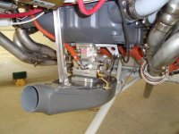
My question or request for help how to best integrate it this induction (I have the cooling air figured out). The issue is when you put the bottom cowl on how do I attach the flex coupling between the inlet ring and air box. The plan is to do it similar to the air inlet. The challenge is how to attach clamps?

My two ideas to make the connection easily when removing and installing lower cowl are:
  • access panel on bottom held on with nut-plates and screws to install clap between flex duct and FAB.
  • Induction extended part is removable with semi ridge duct that just slides on with no clamp, a net or loose fit, accept some leakage.
Never had a Sam James Cowl, so if anyone can chime in and tell me how he does it, or if anyone has a similar installation I would be grateful for tips, pictures, and I'll buy you a bear at SOS tent during air venture, with a value worth 1 million dollars. Ha ha.

NOTE, per "Speed with Economy" placing the induction close to the propeller will increase induction, boosting induction pressure or MAP. I'm a slave to aesthetics, and likely not going to get to the 1" gap needed from the prop blade, but just FYI. (I recall Kent Paser's research showed closer the better, don't recall exact distance but likely in same plane as the cooling air inlets). SCOOP.jpg
 
Last edited:
I have considered mods at the intake, but never executed. My plan was a short rubber snorkel from the fab terminated in a machined or fg circle or cone, leaving it a bit short of the inside of the cowl inlet. Them make a sleeve that is installed from the outside of the cowl through the opening and into the collector on the snorkel. Then a screw or two to hold it in place. Need to modify the fg inlet to mate well with the sleeve and keep drag in check. This can be fg that slips inside the current opening or can be done with newly machined parts and rework the inlet area to accommodate it. That latter makes more sense for you in keeping with round inlets. This can be made to be air tight and capture all the ram pressure. Scat won’t work, as you need rigidity to keep the collector and sleeve tight together. Sleeve is smaller than collector and foam or rubber used to seal.

Only real requirement is the the rubber snorkel is long enough to deal with the engine movement across its isolators. Good news is that there is 2” of fg sleeve inside the cowl that can be cut off to accommodate this length requirement. Even more if you extend the inlet closer to prop.

Yes, I have the sleeve or duct made of diving neoprene, custom made for me. It is a little floppy. Good idea, and here is a variation.

The metal ring could slide in cowl, be held with screws as shown. The neoprene has a slight stretch to get around the machined ring, but still needs a clamp. Once lower cowl is in place, install the removable cowl intake scoop. The metal fitting slides in and has one or two set screws keep it from moving. To remove lower cowl reverse the steps/

The the end of cowl inlet scoop may not even need to removable, the inlet should find it's way home as the lower cowl is lifted into place, and slide into the cowl, with a little help from the cowls open inlet. Again set screws keep metal fitting from moving. The clamps stay attached. Remove set screw or screws, lower cowl and if needed push ring out of cowl. The neoprene is not super ridged like rubber.

SCOOP2.jpg
 
Last edited:
A removable cowl section or a slide-in sure makes lower cowl installation easier.

I gather you have some sort of round to "D" adapter grafted to the airbox. Going with a small inlet and internal diffusion (the case with the stock airbox) means you'll need to be cautious about screwing up that diffusion at the section change.
 
This is a common mod in my part of the world. The ram air inlet on the cowl is made to be removable and it is connected to the FAB by a piece of SCAT. Pic attached to try and explain it better than words.

20240915_091650.jpg
 
Last edited:
To the OPs question, my first RV-10 has the James cowl and associated round cooling and engine air inlets, vertical induction.

The FAB was modified to take a “FAB to round fiberglass” piece (provided by James Aircraft). This attached to SCAT tubing ( with a hose clamp). The SCAT tubing was cut ~1”long. When installing the bottom cowl some manipulation of the SCAT hose is needed to makes sure it slips over the engine air inlets ring on the inside. This results in the SCAT tubing being held in place by compression. Flying 14 years and this has work perfectly.

Note - use SCAT not SKEET tubing. SKEET is far too rigged so the engine vibration is not absorbed over the short length of tubing. This risks fatigue cracking of the FAB top aluminum plate.

I modified the stock RV-10 FAB also take the taller E-1000 K&N filter (top plate flipped over). This also provided better alignment to the James Cowl engine air inlet.

On the new RV-10 I have the Cold Air Sump horizontal injection, so still working to figure out a low pressure drop filter set up (I do not like the non-filtered ram air options). I suspect (as Dan Horton posts) a removable inlet ring section will be needed.

Carl
 

Attachments

  • RV-10 air box.jpeg
    RV-10 air box.jpeg
    211.9 KB · Views: 88
Take a look at this thread, you might get some ideas.

Scoop was installed with quarter turn fasteners, hook up for induction air was a slide on setup with a custom fitted tube made from rolled up wet suit material.

 
My inlet section is not part of the lower cowl, but mounts to it with 7 mil-spec fasteners. It is the entire airbox, filter and all, as I wanted the largest area air filter I could fit. I use a section of silicone air duct to connect the 2. The assy slides onto the serve inlet fitting I made and then is fastened to the cowl. Easy on/off. I originally secured the clamps to the servo fitting, easily accessed with upper cowl off. But it fits so tightly that there is no detectable MAP drop, so I dispensed with it.Screenshot_20250422_143035_Photos.jpg
 
Last edited:
I've seen a number of planes with the extended inlet. They all shared the same flaw - the edges of the inlet were relatively sharp. Sounds counter-intuitive, but you want them similarly radiused as the original and as the stock cooling inlets are. This allows the air flow to "split" at the appropriate place, depending on conditions. A sharp edge forces the split in flow at a point which may only be optimal at one set of conditions. Almost no aircraft have wings with a sharp leading edge (F-104 is the only one I know of, there are probably more), presumably for the same reasons.
 
A removable cowl section or a slide-in sure makes lower cowl installation easier.

I gather you have some sort of round to "D" adapter grafted to the airbox. Going with a small inlet and internal diffusion (the case with the stock airbox) means you'll need to be cautious about screwing up that diffusion at the section change.

"I gather you have round to "D" adapter grafted to the airbox. " Yes Sir, you gather correctly, but "have" is in my head. Glue and string,, foam mold will sacrifice their lives in this adapter.

Tes Sir, right again, I will be thinking about fluid dynamics, abrupt changes, gaps, lips. The other way is go stock and leave the induction alone. It did make putting the lower cowl back on a challenge solo.

The round inlets are happening. I think. I want the challenge and dare the fiberglass daemons.
 
I've seen a number of planes with the extended inlet. They all shared the same flaw - the edges of the inlet were relatively sharp. Sounds counter-intuitive, but you want them similarly radiused as the original and as the stock cooling inlets are. This allows the air flow to "split" at the appropriate place, depending on conditions. A sharp edge forces the split in flow at a point which may only be optimal at one set of conditions. Almost no aircraft have wings with a sharp leading edge (F-104 is the only one I know of, there are probably more), presumably for the same reasons.
Yes Sir. I understand. I have read all the publications... The machined inlet is radiused. I bought them from Dave Anders' of RV-4 CAFE foundation king. So they designed properly. So the cowl will match that radius tangent initially. Some of it will be eye.

As well the Mississippi State Paper from 1970's has some guidance on inlet geometry. To be honest it will be a bit eyeball engineering and whatever I can find to make a radius that looks right.
 
To the OPs question, my first RV-10 has the James cowl and associated round cooling and engine air inlets, vertical induction.

The FAB was modified to take a “FAB to round fiberglass” piece (provided by James Aircraft). This attached to SCAT tubing ( with a hose clamp). The SCAT tubing was cut ~1”long. When installing the bottom cowl some manipulation of the SCAT hose is needed to makes sure it slips over the engine air inlets ring on the inside. This results in the SCAT tubing being held in place by compression. Flying 14 years and this has work perfectly.

Note - use SCAT not SKEET tubing. SKEET is far too rigged so the engine vibration is not absorbed over the short length of tubing. This risks fatigue cracking of the FAB top aluminum plate.

I modified the stock RV-10 FAB also take the taller E-1000 K&N filter (top plate flipped over). This also provided better alignment to the James Cowl engine air inlet.

On the new RV-10 I have the Cold Air Sump horizontal injection, so still working to figure out a low pressure drop filter set up (I do not like the non-filtered ram air options). I suspect (as Dan Horton posts) a removable inlet ring section will be needed.

Carl

Carl nice work. I might check out if Sam James can make me a scoop, but think I can make my own (think) so it fits and looks and functions as I dream of....

The ROUND Cooling Air Inlets are also from Dave Anders. I asked Sam James to make me fiberglass cowl cooling inlets. They took a Splash off their molds and made just the nose inlets, left / right, top bottom. I am splicing them on a Van's Stock Cowl.... Sure I could have bought Sam James. Too late. I never thought to ask about the inlet because I assumed I would make them my self....

Thinking the lower half of the scoop could be split horizontally and have a lower section come off.... That would make the cowl maintenance removal/install really easy. I am really a kiss guy... I want to minimize fasters, fiberglass laps... We shall see. At min a access cover on bottom under the airbox/inlet duct junction may be a compromise. No doubt some cursing will happen getting lower cowl on and off.
 
Last edited:
PaulvS,
Mike S,
RV8RIVETER


Thank you for all your input.... I will read and digest. Great input. If it is not right I'll start over and try try again.
Appreciate it.
 
Yes Sir. I understand. I have read all the publications... The machined inlet is radiused. I bought them from Dave Anders' of RV-4 CAFE foundation king. So they designed properly. So the cowl will match that radius tangent initially. Some of it will be eye.

As well the Mississippi State Paper from 1970's has some guidance on inlet geometry. To be honest it will be a bit eyeball engineering and whatever I can find to make a radius that looks right.
Let me know if you need some help. I made somee bell mouth inlets in the past and made special bits for the lathe to make them.
 
The ROUND Cooling Air Inlets are also from Dave Anders.

Two notes...

There's nothing special about "round", other than being easier to seal to an internal duct, plenum, or airbox.

Dave prefers internal diffusion, which drives some aspects of detail design. The smaller internal diffusion inlets need the bellmouthed rings so they will flow well at aircraft velocity below the optimum for the diameter.

Photo of Dave's cowl with bellmouth aluminum ring. Also note generous external radius, as Alex discussed.

ScreenHunter_2772 Apr. 25 10.07.jpg

Three inlets with diameters for external diffusion. The cooling inlets are theoretically correct, generous external radius, no internal bellmouth required. The airbox inlet is wrong, too sharp, not enough external lip radius. Looks nice, but I probably get some separation and drag there at higher airspeeds. Just failed to think about it back then.

IMG_3696.JPG

Inlets and Bodies.jpg

I asked Sam James to make me fiberglass cowl cooling inlets. They took a Splash off their molds and made just the nose inlets, left / right, top bottom. I am splicing them on a Van's Stock Cowl.... Sure I could have bought Sam James. Too late. I never thought to ask about the inlet because I assumed I would make them my self....

I'm not sure what shapes Jimmy has available now. Smaller diameter James inlets were probably a bit too pointed for external diffusion, so they need internal diffusers. Good match for Dave's rings, but the catch is good diffusers require internal length not available in a stock cowl. The inlet plane is too close to the front of the cylinders.

Long ago I went with external diffusion primarily so I would not need a prop extension with the 390 and a metal Hartzell. No internal diffusers required, thus the short length is fine.

I only bring it up because you mentioned cooling inlets. Not an issue with the long airbox for an updraft sump.

An observation...we have long considered "ram air" to be a big deal, so much so that some builders are even willing to eliminate filtration. Sure, work to gain pressure everywhere you can, but it appears tapered tube intake runners are the real deal.
 
some builders are even willing to eliminate filtration
Old, and logical idea really... remember that Mooney 201 with the 180 ponies up front? Take off on internal filter, once in "clean" air, say 1+Kft, go to ram air. The best of the 2 worlds IMHO.
Most if not all of our pure local aerobatic mounts, namely MSW Votec, fly without any filtration, and have been doing so for many hours over many years. Yes, not operating in a dusty/dirty environment will help...
 
Most if not all of our pure local aerobatic mounts, namely MSW Votec, fly without any filtration, and have been doing so for many hours over many years. Yes, not operating in a dusty/dirty environment will help...
Indeed, and I've got one in my shared hangar, but literally one insect in the wrong place would probably put you in that corn field at the end of the runway.

The following screen grab is stolen from a YT video:

Insect in FM-200.png

And in the summer time, in the clean air of Switzerland, we have a lot of insects.
 
One question - we seem to be focused on the air flow on the outside of the throttle body, but kind of ignore what's happening after the throttle body. I know my FM-200 gets choked a lot going into my Superior cold air sump. @DanH - I recall you were working on some optimizations between the throttle and the sump - did you see any measurable improvement?
 
Two notes...

There's nothing special about "round", other than being easier to seal to an internal duct, plenum, or airbox.

Dave prefers internal diffusion, which drives some aspects of detail design. The smaller internal diffusion inlets need the bellmouthed rings so they will flow well at aircraft velocity below the optimum for the diameter.

Photo of Dave's cowl with bellmouth aluminum ring. Also note generous external radius, as Alex discussed.

Three inlets with diameters for external diffusion. The cooling inlets are theoretically correct, generous external radius, no internal bellmouth required. The airbox inlet is wrong, too sharp, not enough external lip radius. Looks nice, but I probably get some separation and drag there at higher airspeeds. Just failed to think about it back then.

I'm not sure what shapes Jimmy has available now. Smaller diameter James inlets were probably a bit too pointed for external diffusion, so they need internal diffusers. Good match for Dave's rings, but the catch is good diffusers require internal length not available in a stock cowl. The inlet plane is too close to the front of the cylinders.

Long ago I went with external diffusion primarily so I would not need a prop extension with the 390 and a metal Hartzell. No internal diffusers required, thus the short length is fine.

I only bring it up because you mentioned cooling inlets. Not an issue with the long airbox for an updraft sump.

An observation...we have long considered "ram air" to be a big deal, so much so that some builders are even willing to eliminate filtration. Sure, work to gain pressure everywhere you can, but it appears tapered tube intake runners are the real deal.

Interesting, all understood. Your points about internal and external diffusion and " tapered tube intake runners are the real deal", are well said. Pictures helpful, thank you. I will do my best eyeball engineering, one closed, one open with my thumb extended..."looks right:, with all info and advice. I am aware of the physical limitations the geometry of our cowl, prop, and engine set up have, in making cooling challenging. Fun design challenge. Looking for reduction in drag, but other practical goals are part of deviating from plans.

Round is not magic. As you say round makes it easy to connect. P-51 belly scope, not round and considered an aerodynamic and cooling masterpiece, deservingly so in my opinion. Not round.

The "Round" set-ups (if done properly) have lower cooling drag and other benefits that are my Goals.

SOLID DOG HOUSE engine baffle, not to rely on the soft seals rubbing and loading cowl (for cooling). This will reduce wear on cowl fuselage piano hinges and baffle stress. The round inlets as you say easy to seal. although I have seen people keep Van's inlet shape and make a great seals to solid dog houses. Looking at van's stock cowl cooling inlets, the inlet radius are large BTW. so they got the memo.

INDUCTION SCOOP - Ease of cowl installation and good solid leak free connection that does NOT stress the FAB from vibration. Moving the induction closer to prop, having more "diffuser' length will improve flow. Will I get more MP or HP? Will drag be less? Even if miniscule it is OK if I reach my other goals. Since the cowl cooling inlets will definitely be round the induction being round will look better. .

AESTHETICS - Personally I like Van's stock look, a lot. Round is not necessarily better looking, but due to the possible (likely if done proper) lower cooling drag and BETTER SEALING.

PRO / CON of STOCK - Pro easier per plans, done. Con, soft engine baffles on cowl is a wear issue, plus baffle cracks and leak issue, reducing cooling and increasing maintenance. Also Con, broken Van's FAB due to vibration, leaky seal to FAB, and cowl installation difficulty (kind of). These are reasons to go round.
 
Last edited:
Back
Top