
Van's Air Force
You are using an out of date browser. It may not display this or other websites correctly.
You should upgrade or use an alternative browser.
You should upgrade or use an alternative browser.
Fuel Flow Transducer Location
- Thread starter BSRV6
- Start date

Wunderon
Well Known Member
Depends on engine, etc. quite a few threads out there
one to look at http://www.vansairforce.com/community/showthread.php?p=1002607&mode=linear#post1002607
one to look at http://www.vansairforce.com/community/showthread.php?p=1002607&mode=linear#post1002607
Carbed or injected?
Tom
Tom
Raymo
Well Known Member
Crabed and a 0-320 lycoming.
In carbureted engines, the flow transducer should be between the mechanical pump and the carb. The exact location will be dictated by your particular setup/exhaust routing.
Mine is a FloScan in the cockpit, midway between fuel selector and boost pump. Yes, I know not the optimal location, but simple and easy, out of the heat of the engine compartment, and mine is always accurate to within a couple tenths of a gallon at each fill-up. Many are located in the same place without issue. A filter is reccommended upstream of it, however, as it has a small orifice.
Chris
Chris
There are literally 1000's of locations and opinions of where to mount the flow transducers. Typically for carbed engines, between the mechanical pump and the carb is the most optimum location. Injected engines, between the servo and the flow divider. Our opinion is based on data from AirFlow Performance. Don and I have talked about these locations and our theories for them. Don has the flow bench data from his testing.
Firewall locations, although they work for some builders, is not the optimum location.
Tom
Firewall locations, although they work for some builders, is not the optimum location.
Tom
For those with their fuel flow transducer upstream of the fuel pump, are you not concerned about vapor lock?
No - it is under pressure there. It is under suction before the mechanical pump.
Edit - Oops, dyslexic I suppose, upstream (ahead in the flow path) from the mechanical pump will degrade the temperature tolerance and/or vapor pressure tolerance of the fuel system. Mine is between the mechanical pump and the injected fuel distributor. Sorry Michael, thanks for the save.
Last edited:
Tom @ N269CP
Well Known Member
EI's installation manual for the FP-5 meter clearly specifies to install the Red Cube between the engine driven pump and carburetor. I am having mine mounted on the firewall, but piped between the engine driven pump and carburetor...per EI's drawing.
My anecdotal understanding is that the suction flow and discharge flow vs time characteristics for the engine driven pump may not be identical. There may be some built-in volumetric capacitance inside the pump. But I have not seen this characteristic documented anywhere. I will just stick with EI's installation specs.
My anecdotal understanding is that the suction flow and discharge flow vs time characteristics for the engine driven pump may not be identical. There may be some built-in volumetric capacitance inside the pump. But I have not seen this characteristic documented anywhere. I will just stick with EI's installation specs.
Toobuilder
Well Known Member
No - it is under pressure there. It is under suction before the mechanical pump.
For the sake of clarity, "upstream" is by most definitions "before" the mechanical pump.
Anything before the mechanical pump is "upstream" and therefore on the suction side. Given the recent threads by DanH and others looking at the incredibly small internal passages of these devices, any suction side mounting should be considered a really bad idea.
Yes, there are thousands flying with them on the suction side - that does not change the fact that its a bad idea. After all, there are still people in this day and age that take up smoking cigarettes too. Just because people do something does not make it smart.
While I agree the flow sensor is best located between the throttle body and the spider, I offer that this is not a ?do or die? issue.
As there are many RV-10s flying with the flow sensor in the tunnel per the Van?s plans (mine included) we have data available on flow accuracy in this location. For my plane, the fuel total has always been within 0.2 gallons on fill up.
My first plane had it just before the spider and it worked fine. Still deciding where to put it on the new RV-8 project. As I know accuracy is good in various locations, I?m now biasing the decision more toward best place for heat, vobration and mechanical aspects of the mount.
Carl
Toobuilder
Well Known Member
Accuracy is not the issue. The consideration that makes a suction side installation undesirable is the incredible restriction that it creates. We go to great lengths (or should) to minimize suction side restriction by minimizing the use of 90 degree fittings, buy high flow filters, reduce the length of tube, etc... To then throw this device with a pinhole through the middle of it right in the whole mess defeats all of that prior design elegance.
The harder the fuel pump has to draw on this restriction, the lower the system pressure is. The lower the pressure is, the easier that vaporization occurs. Throw some warm temps and/or a low vapor pressure fuel and suddenly you have idle problems and/or vapor lock.
As many will attest it does work, but sometimes it does not.
Last edited:
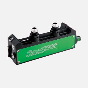
ultrasonic fuel flow sensors
We just need to knock one digit off the price of these ultrasonic fuel flow sensors and then it won't matter much where we put them. I'm sure they'd be even happier inside the cockpit.
http://www.reventec.com/product-category/flow-sensors/
We just need to knock one digit off the price of these ultrasonic fuel flow sensors and then it won't matter much where we put them. I'm sure they'd be even happier inside the cockpit.
http://www.reventec.com/product-category/flow-sensors/
I just bought an RV 10 with a O-540. I do not see the flow meter in the engine compartment so I think it's in the tunnel. My fuel flow fluctuates up and down by around 2 GPH. The engine runs fine and the apparent fluctuation does not seem to an affect the engine performance and the meter is accurate in total but I don't like the fluctuation and I'm going to open up the tunnel and see what's there and move the red cube, if it has a red cube, to downstream of the engine driven pump. Maybe I'll replace it with a new one as well as the airplane has about 700 hours on it.
Since you have a carb you may be seeing the needle valve opening and closing. I seem to recall that there may be a setting for carbs that does some averaging?I just bought an RV 10 with a O-540. I do not see the flow meter in the engine compartment so I think it's in the tunnel. My fuel flow fluctuates up and down by around 2 GPH. The engine runs fine and the apparent fluctuation does not seem to an affect the engine performance and the meter is accurate in total but I don't like the fluctuation and I'm going to open up the tunnel and see what's there and move the red cube, if it has a red cube, to downstream of the engine driven pump. Maybe I'll replace it with a new one as well as the airplane has about 700 hours on it.
In the -10 the plans call for the cube to be upstream from the mechanical pump-but downstream from the aux pump. Another good reason to run the aux pump when down low.
Refering to EI FT-60 "red cube". Pressure drop is 0,5 Psi @ 28 USG per hour.
This means that the pressure drop @ 14 USG per hour is 0,5/4 = 0,125 Psi.
It's so low that it's hard to messure. I would not be concerned about this pressure drop.
To calculate pressure drop at other FF, see the manual.

 www.aircraftspruce.com.au
Good luck
This means that the pressure drop @ 14 USG per hour is 0,5/4 = 0,125 Psi.
It's so low that it's hard to messure. I would not be concerned about this pressure drop.
To calculate pressure drop at other FF, see the manual.
Electronics International Fuel Flow Transducer FT60 | Aircraft Spruce Australia
Electronics International Fuel Flow Transducer FT60 Flow Transducer. For use in Aircraft with engine-driven fuel pumps & Horsepower up to 350 HP.
Good luck
Mine was originally mounted on the firewall upstream of the pump with a 90 degree fitting on inlet and outlet. I fought pressure and flow fluctuations for years, changed two engine driven pumps, cleaned filters, insulated the tunnel, etc., etc. Finally relocated the flow transducer between the servo and the flow divider and just like magic all the problems went away. I know you have a carburetor but I would recommend the absolute minimum number of flow restrictions on the suction side of the pump (no transducer, minimum possible 90 deg fittings, etc.) and put the flow transducer between the pump and carburetor. Anything else is begging for trouble.
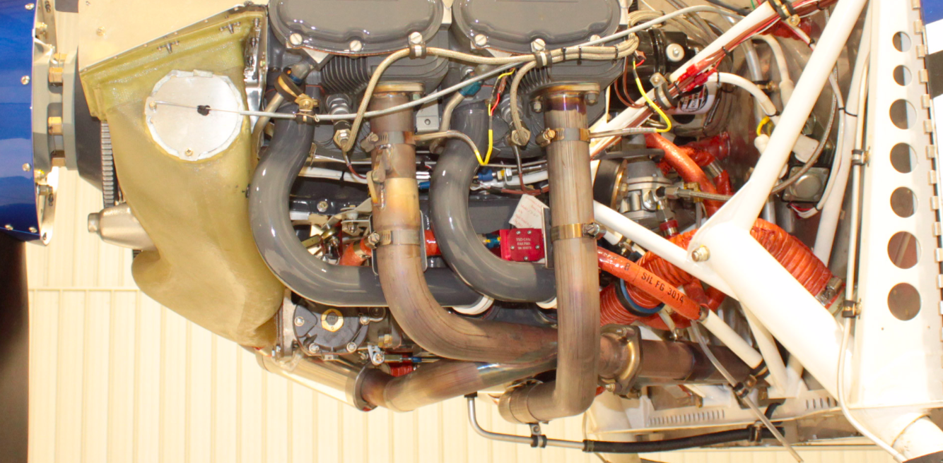
I didn't see any reason to reinvent the wheel here. I mounted mine to the intake runners on the left side as recommended for the RV14. You can see the location in the picture up in post #3.
I'm in phase 1 with only a few hours on it, but it seems to work fine there.
I'm sure that the kit Tom sells to mount it up by the distribution spider would work great as well. That's basically where Cessna amounts them on the fuel injected 172's.
I'm in phase 1 with only a few hours on it, but it seems to work fine there.
I'm sure that the kit Tom sells to mount it up by the distribution spider would work great as well. That's basically where Cessna amounts them on the fuel injected 172's.
Same here, but with a couple of modifications:I didn't see any reason to reinvent the wheel here. I mounted mine to the intake runners on the left side as recommended for the RV14. You can see the location in the picture up in post #3.
I'm in phase 1 with only a few hours on it, but it seems to work fine there.
I'm sure that the kit Tom sells to mount it up by the distribution spider would work great as well. That's basically where Cessna amounts them on the fuel injected 172's.
1: I used AN4 bolts to secure the cube to the cushioned clamps.
2. Drilled the holes in the clamps to 1/4 to accommodate the AN4 bolts
3. Installed additional washer between the cushion clamp “ears” to keep the spacing better. The intake runners are a little larger than the cushion clamp diameter IIRC.
4. Installed another washer between the red cube bottom and cushion clamp ear to stand-off the cube.
5. Installed heat shields on the #2 headers facing the cube
6. Replaced the AN/NPT fittings with straight (not 45°) steel fittings
7. Custom length hoses on both sides of cube to allow for “gentle” bends.
8. Ensure wires and connections from cube move with the cube and not fixed or moving against the cube.
Pictures to follow if anyone is interested.
I did something similar. Seems like very few systems installations are really "standard"Same here, but with a couple of modifications:
1: I used AN4 bolts to secure the cube to the cushioned clamps.
2. Drilled the holes in the clamps to 1/4 to accommodate the AN4 bolts
3. Installed additional washer between the cushion clamp “ears” to keep the spacing better. The intake runners are a little larger than the cushion clamp diameter IIRC.
4. Installed another washer between the red cube bottom and cushion clamp ear to stand-off the cube.
5. Installed heat shields on the #2 headers facing the cube
6. Replaced the AN/NPT fittings with straight (not 45°) steel fittings
7. Custom length hoses on both sides of cube to allow for “gentle” bends.
8. Ensure wires and connections from cube move with the cube and not fixed or moving against the cube.
Pictures to follow if anyone is interested.
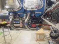
Stainless steel fittings, heat shields, two shorter fuel lines from Tom that accommodated the location on my RV7, etc.
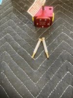
Like you, I didn't care for the slop between the holes in the cube and the provided mounting screws. My solution was to ream out a couple of short lengths of scrap nylon pitot line to 3/16 and slip it over AN3 bolts.
In the second picture below you can see that I used blue adel clamps to mount it to the intake runners. I can't remember the dash number off hand. I want to say I used -25 and vans calls out -26? Whatever, they resulted in a nice fit. For those that are curious, the blue ones are high temp like the white, but they're also impervious to most chemicals. They are crazy expensive if you buy them new and you'd likely have to dip your toes into the jet world to find them in this size, so I'm not advocating running out and buying a bunch just for this application. It was like finding a unicorn when I came across a paper bag full of them in the surplus hardware building at the Yard Store.
Attachments
Last edited:
