
Van's Air Force
You are using an out of date browser. It may not display this or other websites correctly.
You should upgrade or use an alternative browser.
You should upgrade or use an alternative browser.
Engine dehumidifier
- Thread starter Michael Henning
- Start date


Cheap and uses no power...... https://www.canadiantire.ca/en/pdp/dri-z-air-dehumidifier-0790014p.html
It works very well. But be careful with the gathered moisture, it becomes corrosive after being adsorbed by the pellets and dropped into the container. Really not a problem.
............................................. $13.00 on Amazon...............Dri-Z-Air DZA-U Pot...............................................
Last edited:
readings
I connected an in-line sensor (cheap sensor) from the return line to measure the humidity. I connected the Engine Dehumidifying Unit (EDU) (because EDU is better than ED) after a flight, after an hour it peaked at 92% but then dropped to 10% in the next hour. that is the lower limit of this cheap sensor. overall, I like the dehumidifier and I will continue to use it.


I connected an in-line sensor (cheap sensor) from the return line to measure the humidity. I connected the Engine Dehumidifying Unit (EDU) (because EDU is better than ED) after a flight, after an hour it peaked at 92% but then dropped to 10% in the next hour. that is the lower limit of this cheap sensor. overall, I like the dehumidifier and I will continue to use it.
Last edited:
oil appears clearer
I connected a closed loop dehydrator to cycle dry air to the oil filler neck and thru the crankcase vent and run it continuously. When I check the oil level the on the dipstick, it appears clearer or could it be I am imagining this. Is there any way dry air could make oil clearer in the way I'm using it?
I connected a closed loop dehydrator to cycle dry air to the oil filler neck and thru the crankcase vent and run it continuously. When I check the oil level the on the dipstick, it appears clearer or could it be I am imagining this. Is there any way dry air could make oil clearer in the way I'm using it?
Last edited:


Steve, yours was orange media, correct? Just asking.
I used blue media and changed mine out for regeneration last week. It ran all the way from November thru April and could have run much longer, but it had started to turn colors. So it looks like I should be able to get by all winter with one set of media, and we'll have to see how much the summer humidity changes things. Probably not too much since it's all just recirculating in the engine.
2-3 times per year isn't too bad. I'm thrilled with that.
It's been 5 weeks of continuous recirculating flow. This is the result. I added an extra gallon. I'll put it on a timer now.
Steve, This is recirculating in the engine, but how many times have you flown?
If none, you have air leaks. If recirculating and not flying it should run a year without needing to be regenerated. BTDT
Steve, yours was orange media, correct? Just asking.
I used blue media and changed mine out for regeneration last week. It ran all the way from November thru April and could have run much longer, but it had started to turn colors. So it looks like I should be able to get by all winter with one set of media, and we'll have to see how much the summer humidity changes things. Probably not too much since it's all just recirculating in the engine.
2-3 times per year isn't too bad. I'm thrilled with that.
Tim,
Do you measure the humidity in your engine/system? How do you know that it is actually working well
As a reference, mine is setup in a closed loop system (other than exhaust valve or intake valve that might be open. I have a sensor that measures humidity and kicks on the pump when it reaches a certain %. I am using half a gallon in two jars and set up the humidity to go as low as 10% and kick the pump back on when it comes up to 15% so the pump is not running all the time. In the dry N. CA weather, the typical humidity in the engine is between 55-60% after an hour of flying. My first gallon lasted me only three months and I found recharging them, they are not nearly as effective as when they are new.
This time around I am going to take more care in recharging them, too much heat will kill them (turning black)
There have been multiple times that I have observe the pump continuously running, unable to bring the humidity to the 10% level and the silica is still blueish color.
Hope this adds value to everyone's attempt in building/using this.
I'm not anal enough to put a humidity meter on it. The media will turn colors as appropriate. When I ran it open loop, I could see color changing fairly quickly. When I ran it closed loop, it didn't. I'm just trying to keep it all simple, yet effective. I've got 2 systems on 2 planes with 2 jugs of media in each dry case, and the media does a good enough job telling you by color change what the approximate level is likely to be. As far as I'm concerned, if it's pumping air through the media, which it is, it's definitely going to be good enough for me. My cases are sealed air tight enough that you have to fight a suction to open them, so there aren't many places for leaks. I also cap my exhaust pipes, so there's really very limited places for anything to enter the engine. Really just the intake is about it, and even that I plug on one of the airplanes with a cowl plug. I also don't worry about turning off the pumps. They run 24x7x365. It's just an aquarium pump, so not enough to concern me about electric cost. I didn't wait for the media to turn very pink before I changed it. Mine stayed very dark blue all winter, and when I first could see that the outermost layer in the jug was turning pinkish, I decided to regenerate it.
I do find that if I don't pull the dipstick and let the engine release its vapors, the media where the air comes in does turn discolored. So when I changed media, I sucked off the top inch with a vacuum cleaner and threw it away. When I did the regen, I did it for a full 3 hours. I watched a youtube video where a guy tested various time lengths and he saw more and more moisture lost measured by weight, based on time. It does decrease after 3 hours so I left it at that. It turned a dark blue and stayed that way after 3 hours. I also did it at 260 degrees, and did it in a few shallow pans where the media was no more than 1" deep, stirring every 15 minutes or so. I originally tried a large bowl and found that the stuff on top would dry well but lower levels would not. At least not quickly. So keeping it shallow and stirring fixed that.
For desiccant, I bought 5 x 8lb jugs of it. It takes just over 1 jug to fill my two half-gallon jugs for one plane. So basically I have a little less than 6 gallons or so ready in jugs when I need to change it out. I could get by with less, but I figure I'll regenerate them for both planes at the same time so that I can just take over the kitchen a couple times a year for one evening.
I'm definitely feeling very good about how this is going to work for the engines. It helps me worry less about if I'm going to be able to fly often or not. Right now, the answer is not...as I'm furloughed thru at least the middle of August. So with no paycheck its a perfect time to have some good engine preservation if I can only get out every month or so maybe a couple times.
Regarding the capping of the exhaust, I got vinyl caps on Amazon. Also got "remove before flight" keychains. Then put a small hole I the cap and tied the keychain through with rope and ran one end of the rope into the cap through a tight hole, thru a washer, and then tied it in a knot. Then siliconed the washer and rope right to the cap. So it's sealed up, and the remove before flight keeps me noticing the caps. Plus, my air hose going into the breather tube runs right between the exhaust.
This is one of those things that I think many builders should do for their planes. It can only help their investment stay rust free.
Here's a pic of the media color when I changed it. This is about 5.5 months with routine flying most of the winter. You can see the top where the oil vapor discolored some of it. That was my fault. A few times I went flying and immediately put the suction on. I should have let the engine vent a couple minutes first.
Last edited:
Steve, This is recirculating in the engine, but how many times have you flown?
If none, you have air leaks. If recirculating and not flying it should run a year without needing to be regenerated. BTDT
I think this is after 6 flights. the return line humidity sensor would reach 80% after an hour and then drop to 10% over the next hour. 10% is it's lower reading capability. it's a cheap sensor. the return line is plugged into the crankcase breather exit. there is a small vent hole above that so it is probably pulling in some amount of ambient air. a timer will extend the life hopefully by a factor of 2X. I'm OK with that. the dehydrator gives me piece of mind when I don't fly.
Last edited:
......My first gallon lasted me only three months and I found recharging them, they are not nearly as effective as when they are new.
This time around I am going to take more care in recharging them, too much heat will kill them (turning black)
There have been multiple times that I have observe the pump continuously running, unable to bring the humidity to the 10% level and the silica is still blueish color.
Hope this adds value to everyone's attempt in building/using this.
Mehrdad, I would challenge the accuracy your humidity measurement for the engine as it is shut down but believe it is what your set-up measures.
On to regeneration. I get my beads from Sorbent Systems in CA and after lots of research and issues, here is my summary:
"It is recommended the white beads be heated in an oven at 280-300º F for 90 min. The indicator beads (blue/pink) should be baked at for 90 min @ 230-250º F. The color changes long before they are truly regenerated. These temperatures allow variation in actual temperature without damaging the silica gel."
For several reasons, I switched to white beads and find with the 290F regeneration temps the batch lasts longer. I find the oven saturates with moisture and have to open the door several times to clear it. Although they say (documented) use only 2 beads thick, I have good success with 1/4" layer. There are curves for silica gel performance and as temperature increases the relative humidity achieved is reduced, although not enough for us to become concerned. It is really all about dew point temperature.
I think this is after 6 flights. the return line humidity sensor would reach 80% after an hour and then drop to 10% over the next hour. 10% is it's lower reading capability. it's a cheap sensor. the return line is plugged into the crankcase breather exit. there is a small vent hole above that so it is probably pulling in some amount of ambient air. a timer will extend the life hopefully by a factor of 2X. I'm OK with that. the dehydrator gives me piece of mind when I don't fly.
This makes more sense, but the life is much shorter than my experience with 2 quarts with my original recirculating system. If you are going to use the timer (60 min) it will last longer between regenerations in open loop style. You have a huge amount of beads to regenerate. Looking at the numbers you will agree. 10% humidity at room temps is consistent with my testing as well, although the time constant due to design for mine was horrible, and modified it with a tube to blow air directly on the sensor.
I found the almost everything leaked as I tested each container, the pump housings, and the barb fittings. The cheapest jar from WalMart sealed perfectly while the more expensive jars and kitchen containers did not. With a single pass system the leak issues are less challenging. YMWV
I would not be without a dryer!!!! So NO challenge to that, regardless of the details.
Last edited:
Bill,Mehrdad, I would challenge the accuracy your humidity measurement for the engine as it is shut down but believe it is what your set-up measures.
Can you please elaborate on this, I am not sure if I am getting the meaning all well. FWIW, I semi trust the sensor accuracy as when I check the standard weather report, it jibs down with what the sensor is reporting.
Any info on where you get your beads or type of beads that you have had better luck with it. My first try was in the Microwave which made a huge mess as the beads headed up the plastic container and poured out. We still find the beads here and there in our house.
For the last couple of times, I have tried them in the oven, at 185F for 90 minutes. My way of indication has been change of color, perhaps I should not use the color as a way of indication since I found them very ineffective when I used them. I can see the humidity goes down from 50% to about 30% and then struggles to go below that. With the new beads, it takes 10-15 minutes to go from 50% to 10%
Mehrdad,
I can tell you that you'll want to get at least near 250F if you're going to regenerate them, and my experience while doing the task was the when I had them too thick in a layer, I could stir them all and they would be pinkish on the bottom and blue on top. After I stirred them enough that they were all blue, I took them out and let them cool so I could put them back in the jugs. I was surprised to see that they then all turned slightly pinkish again. That told me that I could be fooled by the heat changing their color without the beads actually being fully regenerated.
So that's why I watched a little videos on regeneration and came up with doing it for at least 3 hours. When I did that, in shallower pans (I used multiple 13x9 pans on 2 oven shelves) and stirred them occasionally, they stayed dark blue when I got all done and were indistinguishable from a brand new bottle of beads that I had. Stirring them also gives the benefit of opening the oven to vent moisture.
So I think you'll have much better luck once you try it again with higher temperatures and some different techniques. It wouldn't hurt to run them more than 3 hours if want to get the absolute most benefit out of the process, too.
As you found, I don't think the microwave is the right way to go for us on this project. And like you, I found that these beads bounce a lot when you pour them and I was chasing the ones that flew out for a while. We found one yesterday under something on the counter.")
I can tell you that you'll want to get at least near 250F if you're going to regenerate them, and my experience while doing the task was the when I had them too thick in a layer, I could stir them all and they would be pinkish on the bottom and blue on top. After I stirred them enough that they were all blue, I took them out and let them cool so I could put them back in the jugs. I was surprised to see that they then all turned slightly pinkish again. That told me that I could be fooled by the heat changing their color without the beads actually being fully regenerated.
So that's why I watched a little videos on regeneration and came up with doing it for at least 3 hours. When I did that, in shallower pans (I used multiple 13x9 pans on 2 oven shelves) and stirred them occasionally, they stayed dark blue when I got all done and were indistinguishable from a brand new bottle of beads that I had. Stirring them also gives the benefit of opening the oven to vent moisture.
So I think you'll have much better luck once you try it again with higher temperatures and some different techniques. It wouldn't hurt to run them more than 3 hours if want to get the absolute most benefit out of the process, too.
As you found, I don't think the microwave is the right way to go for us on this project. And like you, I found that these beads bounce a lot when you pour them and I was chasing the ones that flew out for a while. We found one yesterday under something on the counter.
I used to use our oven set to 250 for a few hours to dry the beads which were in a 10"x14"x2" pan. Used to stir them a few times while drying. I now use an old crock pot that we had laying around. Dump all the beads in and run it on low (only has low or high settings) leaving it overnight. I usually try and remember to stir them once after a few hours to let the moisture out and mix the beads. I also leave the lid cracked open an 1/8" to vent the moisture. Next day turn the pot off, close the lid fully and let it cool for hour or two. Beads come out a very dry dark blue every time. One of the guys on the field drys his in a microwave. Many small thin batches. I never liked the idea much...too much work.
Bill,
Can you please elaborate on this, I am not sure if I am getting the meaning all well. FWIW, I semi trust the sensor accuracy as when I check the standard weather report, it jibs down with what the sensor is reporting.
Any info on where you get your beads or type of beads that you have had better luck with it. My first try was in the Microwave which made a huge mess as the beads headed up the plastic container and poured out. We still find the beads here and there in our house.
For the last couple of times, I have tried them in the oven, at 185F for 90 minutes. My way of indication has been change of color, perhaps I should not use the color as a way of indication since I found them very ineffective when I used them. I can see the humidity goes down from 50% to about 30% and then struggles to go below that. With the new beads, it takes 10-15 minutes to go from 50% to 10%
sorbetsystems.com - - look for bulk silica gel in 2-4 mm beads. I posted the temperatures above. Hard to go wrong. I measured temperature excursions during cycles in the oven (thermocouple) and set at 240F it will range between 230F to 250F, which will not damage the indicator beads. A large pan and thin layer with regular opening of the oven door to release the moisture works for me.
I am interested in your system and the humidity controller.
Let's assume blow-by is half air and half exhaust. Exhaust is 1/2 water, so the water content of blow-by is very high, may be 15 times higher than humidity on a hot day. So your % does not sound like an accurate representation of what is really in the crankcase initially, but after circulation for a while, it should be more representative.
Bill,
I am using a Inkbird temp and humidity controller, I am not using the temp control portion only the humidity control side.
https://www.amazon.com/gp/product/B07GQWY9HM/ref=ppx_yo_dt_b_asin_title_o09_s00?ie=UTF8&psc=1
50-60% humidity is what the normal air measures so it is not surprising that after shut down, I get about the same humidity from the engine.
The instruction on the silica that I bought says to heated in the oven at 220 but I was so worried to ruin them (over heating will turn them to black and if black, they are no good any more) that I set the oven at 180. Perhaps I should try higher heat or longer.
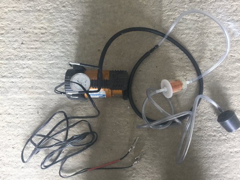
Here is my closed loop dehumidifier made from 90 mm storm water pipe and fittings.
There is an empty chamber at each end and a middle chamber which holds 1 kg of beads. The beads are held in place at each end by metal screens (water tank outlet mosquito screen fitting) which should help promote even air flow through the beads.
The homemade window allows me to see when the beads change colour - clear acrylic 90 mm tube may have been an easier alternative?? Most of the fittings are glued except at the left end where it is pushed together and sealed by the black tape so the beads can be removed to dry. The 90 mm Tee piece at the other end stops it rolling around. The humidity meter probes and air in and out tubes go into the empty end chambers. The blue tube is air out after being sucked through the beads.
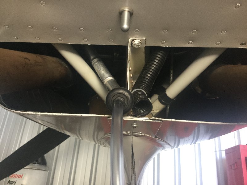
Rubber chair leg ends (from Bunnings (Australia) connect to the oil filler tube and breather outlet. The black rubber is reasonably soft and flexible and fits snugly - 38 mm for the oil filler and 16 mm for the breather. Note I have the antisplat oil separator but the outlet is at the cowl air outlet so is easily accessible.
I don’t have mains power in the hangar so use a 12 volt deep cycle battery. The two humidity meters with probes, aquarium pump, timer, solar panel and charge controller are all inexpensive items from eBay. The little motor pumps plenty of air but only seems to work sucking rather than blowing through the beads. The timer turns on for 20 minutes 3 times a week.
I take out the dipstick and connect this to the breather outlet for a few minutes to purge the hot moist air before connecting the dehumidifier.
Fin 9A
There is an empty chamber at each end and a middle chamber which holds 1 kg of beads. The beads are held in place at each end by metal screens (water tank outlet mosquito screen fitting) which should help promote even air flow through the beads.
The homemade window allows me to see when the beads change colour - clear acrylic 90 mm tube may have been an easier alternative?? Most of the fittings are glued except at the left end where it is pushed together and sealed by the black tape so the beads can be removed to dry. The 90 mm Tee piece at the other end stops it rolling around. The humidity meter probes and air in and out tubes go into the empty end chambers. The blue tube is air out after being sucked through the beads.
Rubber chair leg ends (from Bunnings (Australia) connect to the oil filler tube and breather outlet. The black rubber is reasonably soft and flexible and fits snugly - 38 mm for the oil filler and 16 mm for the breather. Note I have the antisplat oil separator but the outlet is at the cowl air outlet so is easily accessible.
I don’t have mains power in the hangar so use a 12 volt deep cycle battery. The two humidity meters with probes, aquarium pump, timer, solar panel and charge controller are all inexpensive items from eBay. The little motor pumps plenty of air but only seems to work sucking rather than blowing through the beads. The timer turns on for 20 minutes 3 times a week.
I take out the dipstick and connect this to the breather outlet for a few minutes to purge the hot moist air before connecting the dehumidifier.
Fin 9A
Last edited:

Dean Pichon
Well Known Member
If you have a 3D printer, you can make this plug that a friend designed for the oil filler:
https://www.prusaprinters.org/print...NIhYjMy7cGr0DBemezqKXDX9dToSilOCXkm-tOtpId5Kg
My brother-in-law just printed this cap for me using the model at the link above, but it printed a bit "small" Could there be more than one size of filler cap? He also printed this adapter part at the same time and it fits perfectly, so I would not expect there to be a scaling issue. Thoughts anyone?
https://photos.app.goo.gl/vrHAZLRwHX1cP1Zj8
https://photos.app.goo.gl/Wmyr9eiPuEuFZVPM7
Thanks,
filler caps
Salut Dean - I printed it using "shapeways" web service for my Mattituck TMX IO-360 and it fit perfectly. Any chance it's a problem with his 3d printer or the scaling? If you want to fly over LSGY you can have a look at mine in person.My brother-in-law just printed this cap for me using the model at the link above, but it printed a bit "small" Could there be more than one size of filler cap? He also printed this adapter part at the same time and it fits perfectly, so I would not expect there to be a scaling issue. Thoughts anyone?
https://photos.app.goo.gl/vrHAZLRwHX1cP1Zj8
https://photos.app.goo.gl/Wmyr9eiPuEuFZVPM7
Thanks,
Dean Pichon
Well Known Member
Salut Dean - I printed it using "shapeways" web service for my Mattituck TMX IO-360 and it fit perfectly. Any chance it's a problem with his 3d printer or the scaling? If you want to fly over LSGY you can have a look at mine in person.
Hi Mickey,
Thanks for the offer. I'd love to swing by to test fit your cap on my engine, but LSGY is a bit beyond the range of my -4
There are 2 different sizes for the lycoming oil filler ... I forget offhand what they are, but they differ by 1/8" (I think). Your engine may have the other size. Had a similar issue on one I printed for a friend.
Interesting. My printed one appears to be roughly an 1/8" smaller than my dip stick cap. I may give Lycoming a call to see if they can shed any light ont this.
Thanks,
Many very creative and elaborate systems presented here. Thanks very much to all.
I have been operating the Black Max system on my airplanes for several years now and I was wondering if anyone else has had any experience with this high tech (and expensive) setup. <SNIP> These devices (supposedly) remove the humid air in the crankcase, evaporate the moisture from the humid air and replace it with dry air, but the breather tube is not plugged for this operation. I was looking for a simple way to check the humidity in the crankcase after treatment to verify that the Black Max was working such as a hand held electric hygrometer.
Anyway, I guess I'll just have send the Black Max back to the manufacturer for verification of it's working condition
Thanks again for all the posts.
Last edited by a moderator:
Old threads are full of great info! I'm using this "need" of a dehumidifier build to learn a few new skills. In other words, I'm taking the overkill approach for the sake of some fun education! It sounds like the closed system is the way to go in terms of efficiency and desiccant longevity, but it would still be beneficial to somehow purge the engine of those post-flight oil vapors. I could just hang out for a bit while it vents and then plug in the dehumidifier, but where's the fun in that? I decided to design a system that allows me to connect it into the engine right after flight, but also does a purge of vapors before dehumidifying.
The core design is like everyone else's - an aquarium pump, desiccant, and tubes going to the oil filler and breather. To allow for the hybrid open/closed system, I'm using an Arduino to control solenoid air valves that alter the path of the air coming from the engine and to the pump. When I power on the control board, the pump turns on and a solenoid opens and routes the return air flow from the breather so that it just dumps into the open air. In this position, the pump also draws from room air so it's not fighting a vacuum. After one hour of purging the crank case air, the solenoids switch the valve positions and the open system is turned into a closed loop and the air is routed through the dessicant.
That would be enough to call it quits, but I wanted to learn a little more about coding the Arduino. I added two temp/humidity sensors. One is to read ambient air and the other is reading the air coming out of the breather. After the hour vapor purge and the beginning of the closed system, the pump stays on, but is now controlled by humidity readings instead of time. It will continue to run until the humidity of the engine is 20% or lower, then it shuts off. When the humidity climbs back up to 30%, the pump will cycle back on.
I am waiting on a couple of relays (switching over to optocoupler relays), then I'll figure out the best form factor and find/build an enclosure and post some pictures. What a fun project to learn some new skills on! I'm amazed at how inexpensive all of the Arduino related stuff is and how much you can do with it.
Last edited:
Pilot135pd
Well Known Member
I still have the dehumidifier for the interior of my plane and another for the engine, but with the new hangar/home I just built I installed this 5 ton unit that dries up all of the air very quicklyOld threads are full of great info! I'm using this "need" of a dehumidifier build to learn a few new skills. In other words, I'm taking the overkill approach for the sake of some fun education! It sounds like the closed system is the way to go in terms of efficiency and desiccant longevity, but it would still be beneficial to somehow purge the engine of those post-flight oil vapors. I could just hang out for a bit while it vents and then plug in the dehumidifier, but where's the fun in that? I decided to design a system that allows me to connect it into the engine right after flight, but also does a purge of vapors before dehumidifying.
The core design is like everyone else's - an aquarium pump, desiccant, and tubes going to the oil filler and breather. To allow for the hybrid open/closed system, I'm using an Arduino to control solenoid air valves that alter the path of the air coming from the engine and to the pump. When I power on the control board, the pump turns on and a solenoid opens and routes the return air flow from the breather so that it just dumps into the open air. In this position, the pump also draws from room air so it's not fighting a vacuum. After one hour of purging the crank case air, the solenoids switch the valve positions and the open system is turned into a closed loop and the air is routed through the dessicant.
That would be enough to call it quits, but I wanted to learn a little more about coding the Arduino. I added two temp/humidity sensors. One is to read ambient air and the other is reading the air coming out of the breather. After the 1 hour vapor purge and the beginning of the closed system, the pump stays on, but is now controlled by humidity readings instead of time. It will continue to run until the humidity of the engine is 10% or lower, then it shuts off. When the humidity climbs back up to 20%, the pump will cycle back on.
I am waiting on a couple of relays (switching over to optocoupler relays), then I'll figure out the best form factor and find/build an enclosure and post some pictures. What a fun project to learn some new skills on! I'm amazed at how inexpensive all of the Arduino related stuff is and how much you can do with it.

Which Arduino air valves did you use? The only ones I can find are very small diameter.The core design is like everyone else's - an aquarium pump, desiccant, and tubes going to the oil filler and breather. To allow for the hybrid open/closed system, I'm using an Arduino to control solenoid air valves that alter the path of the air coming from the engine and to the pump. When I power on the control board, the pump turns on and a solenoid opens and routes the return air flow from the breather so that it just dumps into the open air. In this position, the pump also draws from room air so it's not fighting a vacuum. After one hour of purging the crank case air, the solenoids switch the valve positions and the open system is turned into a closed loop and the air is routed through the dessicant.
That would be enough to call it quits, but I wanted to learn a little more about coding the Arduino. I added two temp/humidity sensors. One is to read ambient air and the other is reading the air coming out of the breather. After the 1 hour vapor purge and the beginning of the closed system, the pump stays on, but is now controlled by humidity readings instead of time. It will continue to run until the humidity of the engine is 10% or lower, then it shuts off. When the humidity climbs back up to 20%, the pump will cycle back on.
Also, which humidity sensors are you using? I've tried the dht11 and dht22 sensors without much success.
Thanks for this
I'm not using the tiny air valves. I'm using a couple that are similar to this: https://www.amazon.com/gp/product/B07QNK2M2M/ref=ppx_yo_dt_b_asin_title_o00_s00?ie=UTF8&th=1 (important that they can be operated without any PSI to help push the valve slide - most require some residual pressure to help the electrical portion out. I originally wanted a 5/2 solenoid since it would do everything I needed vs 3 different 2 way solenoids, but the 5/2's I could find can't work with 0 PSI. The ones that can are much more expensive). I use relays to deal with the power and I control the relays with the Arduino.Which Arduino air valves did you use? The only ones I can find are very small diameter.
Also, which humidity sensors are you using? I've tried the dht11 and dht22 sensors without much success.
Thanks for this
I'm using the DHT22 sensors. So far they seem to be working ok, at least when comparing with other humidity sensors I have in the house. I haven't put this on a live engine yet - just testing it on my pickled engine. I really only need the closed loop system at this point since my engine isn't running yet, but figured I'd play around and see if I can get the hybrid approach working for the day I move it all to the hangar and start flying!
Dean Pichon
Well Known Member
In addition to photos and parts list, would you be able to post the code? Thanks!I am waiting on a couple of relays (switching over to optocoupler relays), then I'll figure out the best form factor and find/build an enclosure and post some pictures. What a fun project to learn some new skills on! I'm amazed at how inexpensive all of the Arduino related stuff is and how much you can do with it.
Sure thing. I'm making some changes to clean up the design and code first, but once I'm done with that I'll post an update with details.In addition to photos and parts list, would you be able to post the code? Thanks!
In terms of the code - here's the big secret that software engineers on VAF will crucify me for... I used ChatGPT to generate the code! I know some basic coding and could have written it all from scratch, but I wanted to see if AI could spit out something usable. I wrote out all of my requirements in plain English (indicating hardware used, which Arduino board I had, basic architecture, and what I wanted the program to do), then told ChatGPT to write the code for it. Within 5 seconds, I had the code to copy to the Arduino. It would probably make an experienced coder gasp, but hey, it worked! It's simple enough that if I want to change any parameters, like time limits or sensor readings, I can easily identify where to do that and update the code manually.
I'm using the SHT85 with an ESP32 and it works pretty well, and the numbers seem to be as accurate and consistent as the datasheet promises. I use it to see if my black max is still working right, and sadly it struggles. ChatGPT is great when it works, but be sure to check the code carefully - I've seem some things that were pretty surprising!
For sure. Using it was really more about the experiment. This is super simple logic/code, so I wanted to see how it handled it. It's not perfect, but it really is a great starting point for tweaking vs doing it all from scratch.ChatGPT is great when it works, but be sure to check the code carefully - I've seem some things that were pretty surprising!
Last edited:
I like data. Only data shows me that my engine is dry. I learned that my engine is at less than 16% humidity because I can see the data, and the beads will be nice and blue after it rises past 25%. So I dry the beads out before they turn color....data is good.Many very creative and elaborate systems presented here. Thanks very much to all.
I have been operating the Black Max system on my airplanes for several years now and I was wondering if anyone else has had any experience with this high tech (and expensive) setup. <SNIP> These devices (supposedly) remove the humid air in the crankcase, evaporate the moisture from the humid air and replace it with dry air, but the breather tube is not plugged for this operation. I was looking for a simple way to check the humidity in the crankcase after treatment to verify that the Black Max was working such as a hand held electric hygrometer.
Anyway, I guess I'll just have send the Black Max back to the manufacturer for verification of it's working condition
Thanks again for all the posts.
So, I got a humidity indicatory from Amazon. They are not expensive at all. When you connect the Black Max to your engine...I suspect its connected to the oil filler tube. If you plug your intake and your exhaust then the all air exits out the crank case breather. You want to sample that exit air.
Get a clear container, place the humidity indicatory in the container then plumb some tubing from the breather tube to the container with your humidity indicator in it. You'll also have to have an exit port so air will blow out the container.
I use rubber grommets and Rubbermaind Brilliance are the excellant containers. Drill a hole (step drill bit) in the container to receive the grommet (the grommet that is sized for your tubing). Then all the air passes thru your container and past the humidity indicator.
GROMMET

AN931 Elastic Grommets | Aircraft Spruce ®
AN931 Elastic Grommets Flexible grommets, made of black synthetic rubber to specification MIL-G-3036. Resistant to hot oil & coolant. Used to protect tubing, wiring and control cables where they pass through bulkheads & fir...
HUMIDITY INDICATOR
FOOD STOREAGE CONTAINER
Last edited:
