Van's Air Force

The definitive Van's Aircraft support community! Buying, building or flying an RV? Join our exclusive family of mentors and enthusiasts!

EMag issue

YellaDawg

Well Known Member
Sponsor
150 hours dual emags on IO390 in RV8. started with a "stumble" at low RPMs and not noticeable at higher RPMs, now noticeable. I think my left mag is not running internally. Here is my check:

Grounded the right mag at 1200 rpm, killed internal power on left mag and rpm went to zero and engine quit.
Grounded the left mag at 1200 rpm, killed internal power on right mag and rpm was steady and engine remained running.

My plan is to remove both mags for service. But at 150 hours???

I did a pull test on wires and all are attached, cleaned injectors, no change, plugs have 25 hours on them (issue started before new plugs)

Anything else I should check before I take them off?
 
Grounded the right mag at 1200 rpm, killed internal power on left mag and rpm went to zero and engine quit.

I'm confident you meant to write "killed external power". If you were conducting the test at typical RPM for the runup pad (1800 or so), then yes, your left internal generator is dead as canned tuna.

My plan is to remove both mags for service. But at 150 hours???

As noted elsewhere, self-powered is a great sales feature.
 
FwIW- my mags will not supply spark at 1200rpm. I need a bit more for full self exciting capability. Still seems like the left mag internal needs repaired.
 
FwIW- my mags will not supply spark at 1200rpm. I need a bit more for full self exciting capability. Still seems like the left mag internal needs repaired.
My experince over 20 years with dual pMags. The internal generator will keep the fan running down to ~900 RPM or so. Your’s dies at 1200. Does it still work at 1500?

Working other pMag installs I’ll also note that for whatever reason builders get bent around the axle with their “test” switch, as in wiring mistakes when using a three position toggle switch. Same for using an old school Cessna key switch. I only use an on/off ignition toggle switches and pull-able breaker I suggest verifying wiring as the first step.

Side note - check that you grounded the pMags locally on the engine.

If after verify your symptoms the problem persists, contact eMag for repair.

Carl
 
Last edited:
I’ve had Pmags on several airplanes and they would self sustain to ~800 RPM as advertised. Much above that would indicate a problem to me.
 
I’ve had Pmags on several airplanes and they would self sustain to ~800 RPM as advertised. Much above that would indicate a problem to me.
The manual says that generator cut out tests will vary by engine, fuel system (carb vs injection) and other things.
 
Sounds like ONE is bad...not sure why you'd want to pull both unless they need the bearing upgrade. Just because one failed at 150 hours doesn't mean the other is about to fail as well.
 
I actually had this happen a few weeks ago. Newly rebuilt engine, new fuel injection and had a stumbling idle at around 800 RPM. It felt like a skip or timing hunting or like a little stumble. A little rumble but only at idle or around 800RPM. High power was completely fine, no issue

My first thought was fuel so chased the idle mixture control thinking that was my issue. However enrichening it would help to mask the issue while leaning would make it worse. Checked all injectors. Checked all the intake and exhaust for leaks and cracks, smoke tested with no luck.

I also have dual p mags
I changed the right mag to a regular slic and the problem still persisted. So put my pmags back on. Figured if it was a timing issue then changing one mag gave me a 50/50 chance of catching it. I didn't want to believe it could be a mag issue because they only had 40-50 hours on them.
What the heck is going on i thought... driving me nutz... I know you can get a rough idle during break in but this doesn't feel right.
I don't have independent switches for my pmags. Just the left right both switch. So my only way to test my internal generator on my pmags is to kill all ship power (master and avionics off) with engine running and RPM above 800 and see if they still run. Then do a mag check. This is what i did. Right mag ran fine. However, left one grounded and shut the plane off immediately but ran fine with ship power on... SO my left internal generator was internally grounded.

Called Hartzell and spoke with Tyler Burrows and sent him the mag. He had it send back within 3-4 days covered under warranty. Said their was a loose wire or a wire inside that either was not done correctly from the factory or had come loose. Either way he fixed and sent it back quick.
Reinstalled Pmag and rumble stopped..

Just my experience.
Hope it helps.
 
Thanks for all of the replies, they are very helpful just to answer a couple of observations, yes I killed external power and the mag would not run at 1200. It does seem to run at higher RPM as in 1700, but I'll run that again just to to confirm, should run at lower RPMs, LIKE ON FINAL. They were installed Oct 2022 as new, plane first flew 3.23 150 hours since then. I will call Hartzell tomorrow, I'll video the events this afternoon so he can get a good look. I want to send both back, just as a precaution. the switches are all toggles, panel built by Advanced so mostly printed circuits on the panel between toggles etc. Again, Thanks for the help, I'll post the end results, fortunately I have a RV14 to take to Oshkosh, with dual P Mags as well. See you there at the beer bash!

YellaDawg
 
P-Mag states in their manual that you should do a "cut-out test" as part of the annual condition inspection. If they start cutting out at progressively higher RPMs, then something is heading south. For reference, both of mine drop out around 800 RPM when not powered externally.
 
Spoke with Hartzell today and they want both Mags back. Since these are old style, Mfg in 2023 they want to replace them both with the newer style with bigger bearings and rotor.
 
Spoke with Hartzell today and they want both Mags back. Since these are old style, Mfg in 2023 they want to replace them both with the newer style with bigger bearings and rotor.
Was there a fee quoted for these services?
 
One thing that I have realized is I need to change my check procedure to check the internal power at both 1700 and 1200 rpm. I still don’t understand why it runs at 1700 and not at 1200 on internal power. Maybe it is transferring to internal at a higher than designed rpm? Can be a real problem on short final and need all ya got from that mag for a go around!
 
I wouldn’t be comfortable with 1700rpm internal generation, seems like that largely defeats the point.

If your alternator died would you immediately notice? If not, do you have avionics that would quit to clue you in? If so, you would obviously land, but you would need to be very mindful to keep the rpm up.
 
I wouldn’t be comfortable with 1700rpm internal generation, seems like that largely defeats the point.

If your alternator died would you immediately notice? If not, do you have avionics that would quit to clue you in? If so, you would obviously land, but you would need to be very mindful to keep the rpm up.
Very good points. I need to adjust my emag check procedure to find out where each of them quit generating power. Currently I do my checks at around 1700...
 
It’s my understanding that the current (114?) series PMag is designed to run on its internal power as its normal mode. “Emergency” is the ships battery. This is a departure from the 113 and older PMag, which used the ship as primary, and the internal generator as the emergency power. Can anyone confirm this?
 
The P-Mags I got just over a year ago are the P114 series. Everything I've read in the documentation indicates they are to be powered the aircraft bus primarily, with the self-powered feature acting as a back-up. The test buttons they suggest in the manual are push-to-open, indicating that the mags would always be powered from the bus unless the bus lost power.
 
EMAG is wired to ship's power. The EMAG relies on ship's power from 0 RPM to about 800 RPM (varies on each installation). Above about 800 RPM when spinning fast enough to generate internal power, the EMAG switches over to internal power. At that point you could remove ship's power and it would run fine as long as you stay above about 800 RPM.

So really, from 0 to about 800 RPM the only power is ship's power running the EMAG. For startup and backup if the internal power fails. From about 800 RPM and higher the primary is the internal EMAG power with ship's power as a backup.

That is why you want to periodically check the internal power so you know it is working correctly. The test button talked about is to verify if the internal power is working. It can also be done with a switch-breaker. There is a procedure in the manual that describes how to do it.
 
Purely a guess, but it's logical to assume a diode "or" arrangement.
In practice, sure. For the design philosophy change, its noteworthy. We know the pmag requires ships power to start and continue ops under the cutout RPM, but the nominal condition of operation on internal power for the late (114 series) model units is a significant departure from the prior models that relied primarily on ship power nominally. Normally, the change from ship to internal power for any series is seamless and without indication to the pilot. Assuming there is no indication of running on internal or ship power (like some other EI's do), Im wondering how many Pmag drivers are unknowingly flying with failed internal generation?
 
Assuming there is no indication of running on internal or ship power (like some other EI's do), Im wondering how many Pmag drivers are unknowingly flying with failed internal generation?

Lots of them. Most owners are not doing a self-generation check at every runup. Some only check at annual, if ever.

The test buttons they suggest in the manual are push-to-open, indicating that the mags would always be powered from the bus unless the bus lost power.

They are suggested so the pilot can set runup RPM, ground a p-lead, and push the test button for the other mag. If the other mag's internal generator system is operating, you get a normal mag drop and nothing more. If the generator is not not operating, the engine dies.

Some substitute a pull breaker for a standard breaker (or fuse) and test button. Same procedure, but not quite as convenient.
 
Thanks for all of the replies, they are very helpful just to answer a couple of observations, yes I killed external power and the mag would not run at 1200. It does seem to run at higher RPM as in 1700, but I'll run that again just to to confirm, should run at lower RPMs, LIKE ON FINAL. They were installed Oct 2022 as new, plane first flew 3.23 150 hours since then. I will call Hartzell tomorrow, I'll video the events this afternoon so he can get a good look. I want to send both back, just as a precaution. the switches are all toggles, panel built by Advanced so mostly printed circuits on the panel between toggles etc. Again, Thanks for the help, I'll post the end results, fortunately I have a RV14 to take to Oshkosh, with dual P Mags as well. See you there at the beer bash!

YellaDawg
This is an interesting discussion because I'm 15 hours into my engine break in on my 14A (IO-390EXP duel E(P) Mags) I perform the toggle switch checks between 1500-1800 with no issues. I haven't tried the test at a lower rpm. I also have a noticeable miss around 1200-1300 rpm. No issues at my engine breakin power settings (24 to 26MP) (2400-2550rpm) Guess I need to stop by the hartzell tent next week to discuss this with their team. My engine was built up within the chapter 11 timeframe.
 
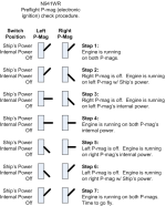
I think Bill nailed this coming up on 20 years ago here: https://repucci.com/bill/electrical.html

View attachment 123419

The only thing I will change as a result of this discussion is to experiment with this process at lower RPMs.
This is very nice documentation and if this airplane was sold to someone else the builder can walk the new owner through the procedure.

As nice as it is, this violates a design rule for me:

No system will significantly depart from a normal certified airplane such that another pilot wouldn’t intuitively know what to do.

In my install you have the following switches in this order

Master on
Aux bus on
IGN 1 on
IGN 2 on
Start
Aux alt on
Avionics on
IGN test up and down

If someone flipped those switches in order the system comes up and tests itself.

When you turn the aux bus on the g3x boots because it has a leg on both buses. That tells you that the emergency battery works and you can watch the oil pressure during start. When you start the aux alt then the aux alternator fault message clears, when you start the avionics master then non critical avionics start and the main alt fault clears.

When the system is up and running there are no warnings or lights, but if either alternator dies, you get lights, and if the SDS swung to backup power, it would also show a fault on its screen.

Because of the completely discrete dual buses and all of the monitoring, the pilot will be clearly told what is going wrong, but there is no limp home switch or bus tie or anything like that. The procedure for dealing with a fault is land when possible.

I understand why the pmag is popular, it’s easy to install and feels like a normal mag with all of the pros, but also the added benefit of EI, but in practice, it doesn’t really have the pros of the mag because the mechanical aspects aren’t as reliable, the system doesn’t work down into idle rpms, and the testing sequence is not obvious to many.

On the EI side, it doesn’t really have the pros of other systems such as on panel monitoring, LOP switch, or the ability to adjust the timing to keep things cool.

The horse is beat to death years ago at this point, but hopefully my post gives someone new to the conversation some information to base their own decisions on….
 
I think Bill nailed this coming up on 20 years ago…

The 114 series PMag did not exist 20 years ago. 20 years ago the electrical architecture philosophy was reversed from the current model. Is this switchology still applicable to a device that uses ships power as the backup power source?
 
Is this switchology still applicable to a device that uses ships power as the backup power source?
Yes it is. This is how mine is wired. Works great.

As nice as it is, this violates a design rule for me:

No system will significantly depart from a normal certified airplane such that another pilot wouldn’t intuitively know what to do.

Not sure what's different from what another pilot would expect. Switches up is the normal state. Moving switches as shown in the diagram will allow testing.
 
Not sure what's different from what another pilot would expect. Switches up is the normal state. Moving switches as shown in the diagram will allow testing.
Because the test requires the switches in specific positions in a specific order. It’s not a simple ground the left then the right.

If I didn’t know the nuance with power automatically switching and the fact that the power source is a distinct mode to be tested apart from cutting the coil/plugs, then I wouldn’t know that I need to specifically kill power to one side and cut the coil on the other.

I suspect that there are a number of airplanes where the internal generator isn’t regularly tested because this nuance may not be understood by the builder, let alone the second owner.
 
I suspect that there are a number of airplanes where the internal generator isn’t regularly tested because this nuance may not be understood by the builder, let alone the second owner.
Absolutely correct - this is one of the challenges of amateur-built aircraft in general, and specifically when they get passed on to new owners.
 
Purely a guess, but it's logical to assume a diode "or" arrangement.
I'm working on the open source ignition system design and this exactly how I have it set up. It's simple and pretty cool.

Here is a summary from the design document (with help from Claude)

The OR-diode is one of those circuits that looks almost too simple for what it does. Here's what's actually happening, built up from first principles.

The basic idea

You have two voltage sources — the aircraft main bus and the backup battery — and you want whichever one is higher to supply the load, automatically, with no relay, no logic, no control signal, no moving parts.

You get this for free from a fundamental diode property: a diode only conducts in one direction, and only when its anode is more positive than its cathode by at least the forward voltage drop (Vf).

1784211678259.png

Each source has its own diode, both cathodes tied together at the output rail. The source with the higher voltage wins — its diode conducts, the other diode is reverse-biased and blocks. No current flows backward through the losing source.


Walking through the three operating states

State 1 — Normal flight (main bus healthy, ~14.2V; backup at ~13.3V):


  • Main bus anode: 14.2V. After D1's forward drop (~0.3V Schottky): cathode = 13.9V at the output rail.
  • Backup anode: 13.3V. D2's cathode would need to be below 13.3V to conduct. It's sitting at 13.9V. So D2 sees 13.3V on its anode and 13.9V on its cathode — reverse biased, blocks completely.
  • Result: main bus supplies everything. Zero current drawn from the backup battery. It just sits there fully charged, waiting.
State 2 — Main bus fails (drops toward 0V):

  • D1's anode falls. The moment it drops below (backup voltage − Vf), D2's forward voltage condition is met and D2 starts conducting.
  • The transition is not instantaneous but it's very fast — diode switching happens in nanoseconds. There is no relay to energize, no comparator delay, no firmware involved. The physics just works.
  • Result: backup battery takes over the load. The output rail sags slightly (by D2's forward drop) but stays live. The ignition system never sees a dropout.
State 3 — Main bus partially degraded (e.g. 12.5V; backup at 13.3V):

  • Main bus anode: 12.5V. D1 cathode would be ~12.2V.
  • Backup anode: 13.3V. D2 cathode would be ~13.0V.
  • D2's cathode (13.0V) is higher than D1's cathode (12.2V), so D1 is now reverse biased. D2 conducts.
  • The backup has taken over even though the main bus is still partially live — because its voltage is higher after the diode drop. This is actually the correct behavior: a degraded main bus is not something you want to draw from.

Why Schottky specifically

Standard silicon diodes have Vf ≈ 0.6–0.7V. Schottky diodes have Vf ≈ 0.2–0.5V depending on current. Two reasons this matters:

  1. Less voltage lost on the output rail. Your backup battery at 12.8V becomes 12.3–12.5V at the load with a Schottky vs 12.1V with silicon. At the low end of battery discharge this headroom matters for the regulators downstream.
  2. The voltage differential determines the switchover point. With two Schottky diodes of matched Vf, switchover happens when the main bus drops below the backup voltage. With mismatched diodes the math shifts slightly — worth using the same part for both D1 and D2, which is why a dual-common-cathode Schottky package like the MBR20100CT is so clean: both diodes are on the same die, thermally matched, identical Vf, in one TO-220 footprint.

The MBR20100CT specifically

This is a dual Schottky, common-cathode package. Both anodes are separate pins (Pin 1 and Pin 3), both cathodes are tied internally to Pin 2 (and to the metal tab). This is exactly the OR-diode configuration in one part:

1784211814566.png
The 20A rating is massively oversized for OASIS's actual current draw — which is intentional. At low currents a 20A Schottky runs cool and its Vf is at the low end of its curve, minimizing the voltage drop on the output rail.

Oh, and you can get 10 or em for ~8 bux.

 
The worry over the P-mag self-powering thing is overblown to the point of absurdity. To get an engine failure you need three completely independent electrical failures:
Mag 1 internal generator failure
Mag 2 internal generator failure
Total main power failure (you can start it with a 9V battery)

The simple self explanatory test procedure in the Pmag manual has been morphed into an ordeal with the clever use of expensive switches.
 
Last edited:
The basic idea

You have two voltage sources — the aircraft main bus and the backup battery — and you want whichever one is higher to supply the load, automatically, with no relay, no logic, no control signal, no moving parts.

You get this for free from a fundamental diode property: a diode only conducts in one direction, and only when its anode is more positive than its cathode by at least the forward voltage drop (Vf).

View attachment 123428
That’s one way. I suggest however for electrially dependent engines you never put an engine load on the output of a master solenoid (main buss or other). The load goes direclty to a battery, before the battery solenoid. So battery, breaker, switch. The simple example of why is your POH immediate actions for smoke in the cabin (open the master solenoid(s). Not a good option if you need either or both of those busses to keep the fan running.

I also suggest two identical ship batteries for electrically dependent engines. Stand alone backup batteries fall short of the minimal time I consider required to keep the fan running (and/or continued IFR flight) and in my experience some builders never check the health of backup batteries once installed. That, and it is not hard get better redundancy using two ship batteries and eliminating backup batteries all together (avionics, engine or both).

The most reliable component in our electrical power distribution installs is a known, healthy battery(s). The Achilles heel are the components in between that healthy battery and where you need power.

If interested I can send you the architecture on how I do this. Send me a DM with your email address.

Carl
 
The worry over the P-mag self-powering thing is overblown...
In this context, I'd offer that the probability of taking the airplane down is on par with any other well maintained EI - unlikely.

That said, when I was flying Pmags I rarely checked the internal generator function, and I suspect that many people still don't. The marketing safety net of the internal generator always being there does shape pilot behavior. But even for those who DO the check at every run up, thats still no guarantee the generator does not fail in flight and the unit switches seamlessly to emergency power without the pilot knowledge. At least one other EI product gives you a warning light that you are off nominal. Pmag (correct me if wrong) lets you fly along with no indication of a failure.
 
The worry over the P-mag self-powering thing is overblown to the point of absurdity. To get an engine failure you need three completely independent electrical failures:
Mag 1 internal generator failure
Mag 2 internal generator failure
Total main power failure (you can start it with a 9V battery)

The simple self explanatory test procedure in the Pmag manual has been morphed into an ordeal with the clever use of expensive switches.

I think the thing most are arguing is that it's harder to detect failures, which is important because a redundant system that don't have a very solid way of validating the redundancy has a habit of silently failing and not being redundant when you need it.

If there are people flying around with failed generators, then this discussion on how to detect the issue isn't overblown.
 
Last edited:
I'm working on the open source ignition system design and this exactly how I have it set up. It's simple and pretty cool.

Here is a summary from the design document (with help from Claude)

The OR-diode is one of those circuits that looks almost too simple for what it does. Here's what's actually happening, built up from first principles.

The basic idea

You have two voltage sources — the aircraft main bus and the backup battery — and you want whichever one is higher to supply the load, automatically, with no relay, no logic, no control signal, no moving parts.

You get this for free from a fundamental diode property: a diode only conducts in one direction, and only when its anode is more positive than its cathode by at least the forward voltage drop (Vf).

View attachment 123428

Each source has its own diode, both cathodes tied together at the output rail. The source with the higher voltage wins — its diode conducts, the other diode is reverse-biased and blocks. No current flows backward through the losing source.


Walking through the three operating states

State 1 — Normal flight (main bus healthy, ~14.2V; backup at ~13.3V):


  • Main bus anode: 14.2V. After D1's forward drop (~0.3V Schottky): cathode = 13.9V at the output rail.
  • Backup anode: 13.3V. D2's cathode would need to be below 13.3V to conduct. It's sitting at 13.9V. So D2 sees 13.3V on its anode and 13.9V on its cathode — reverse biased, blocks completely.
  • Result: main bus supplies everything. Zero current drawn from the backup battery. It just sits there fully charged, waiting.
State 2 — Main bus fails (drops toward 0V):

  • D1's anode falls. The moment it drops below (backup voltage − Vf), D2's forward voltage condition is met and D2 starts conducting.
  • The transition is not instantaneous but it's very fast — diode switching happens in nanoseconds. There is no relay to energize, no comparator delay, no firmware involved. The physics just works.
  • Result: backup battery takes over the load. The output rail sags slightly (by D2's forward drop) but stays live. The ignition system never sees a dropout.
State 3 — Main bus partially degraded (e.g. 12.5V; backup at 13.3V):

  • Main bus anode: 12.5V. D1 cathode would be ~12.2V.
  • Backup anode: 13.3V. D2 cathode would be ~13.0V.
  • D2's cathode (13.0V) is higher than D1's cathode (12.2V), so D1 is now reverse biased. D2 conducts.
  • The backup has taken over even though the main bus is still partially live — because its voltage is higher after the diode drop. This is actually the correct behavior: a degraded main bus is not something you want to draw from.

Why Schottky specifically

Standard silicon diodes have Vf ≈ 0.6–0.7V. Schottky diodes have Vf ≈ 0.2–0.5V depending on current. Two reasons this matters:

  1. Less voltage lost on the output rail. Your backup battery at 12.8V becomes 12.3–12.5V at the load with a Schottky vs 12.1V with silicon. At the low end of battery discharge this headroom matters for the regulators downstream.
  2. The voltage differential determines the switchover point. With two Schottky diodes of matched Vf, switchover happens when the main bus drops below the backup voltage. With mismatched diodes the math shifts slightly — worth using the same part for both D1 and D2, which is why a dual-common-cathode Schottky package like the MBR20100CT is so clean: both diodes are on the same die, thermally matched, identical Vf, in one TO-220 footprint.

The MBR20100CT specifically

This is a dual Schottky, common-cathode package. Both anodes are separate pins (Pin 1 and Pin 3), both cathodes are tied internally to Pin 2 (and to the metal tab). This is exactly the OR-diode configuration in one part:

View attachment 123432
The 20A rating is massively oversized for OASIS's actual current draw — which is intentional. At low currents a 20A Schottky runs cool and its Vf is at the low end of its curve, minimizing the voltage drop on the output rail.

Oh, and you can get 10 or em for ~8 bux.

When I was working through this on my trim controller project, I didn't want the voltage drop and I wanted to make sure the input power system would tolerate huge reverse voltage spikes from unclamped coils and such.

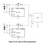
I eventually landed on LM74700: https://www.ti.com/lit/ds/symlink/lm74700-q1.pdf

It's a controller that turns off and on a N-Channel MOSFET so it only has 20mv of drop and when combined with a TVS diode meets ISO7637 transient requirements. It's also AEC Q100 qualified.

I used two of them as described in figure 10-18:

1784216496400.png

My application is less critical than yours, my trim controller isn't needed for the airplane to stay in the air, but I did want it to work even if the main bus shorted to ground, and since I have an aux bus, this made the most sense to me.

I don't have the kit to fully test this, but I have beat on my test board a bit with coils and haven't had any issues.
 
Pmag (correct me if wrong) lets you fly along with no indication of a failure.
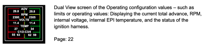
To the best of my knowledge, this is correct. I'd need the engine bridge and EI Commander guys to chime in if they have found the ability to see if the internal generator is working or not. The pmag does report "internal voltage" - perhaps this voltage will change if external power is removed or the generator fails. Here's what I understand that can be seen:

1784216806904.png

There is a note in one of the EI Commander docs I have that says this:
VOLT bus: The internal voltage reported by the ignition. This does not correlate to the aircraft’s voltage.
 
In this context, I'd offer that the probability of taking the airplane down is on par with any other well maintained EI - unlikely.

That said, when I was flying Pmags I rarely checked the internal generator function, and I suspect that many people still don't. The marketing safety net of the internal generator always being there does shape pilot behavior. But even for those who DO the check at every run up, thats still no guarantee the generator does not fail in flight and the unit switches seamlessly to emergency power without the pilot knowledge. At least one other EI product gives you a warning light that you are off nominal. Pmag (correct me if wrong) lets you fly along with no indication of a failure.

Add a fault indication output to the list of potential Pmag improvements. But if you multiply the probability of a power failure that won’t provide the power a 9V battery will with the probability of an internal generator failure even with just one working Pmag it’s still a pretty safe design.
 
Last edited:
If someone would develop an add on LED that said "Ign Emer Pwr" to let the pilot know he was off nominal, I think that would be a valuable bit of SA.
 
The other thing about Pmag failure reports to note is how many there are in operation. A recent VAF aborted poll suggested it might be a big number.
 
If someone would develop an add on LED that said "Ign Emer Pwr" to let the pilot know he was off nominal, I think that would be a valuable bit of SA.
This would make a pmag compliant with my design rules, something on the panel says that something is wrong.

In my trim controller design I use a transistor that is able to sink 100ma of current for this case. The reason is because you can put an LED in place with power on one side and the trim controller on the other and it will light the LED, but you can also wire it into the G3x discrete input and the g3x will internally pull up the line until a fault drives it to ground. In my case I labeled that input Trim Controller, then created an alert that raises a master warning called "Trim Fault".

I probably still wouldn't buy a pmag because of my distaste for unknown timing curves from a black box, because I have no interest in pulling the mag every annual, and because bolting electronics to an engine would violate my own engineering principles..... But... for everyone else that is totally cool with those things, at least you would have a light that tells you what's up.
 
View attachment 123434

There is a note in one of the EI Commander docs I have that says this:

If there was a way to get this on the panel that would be better, I wonder how many people bought a pmag because it's a direct mag replacement, but then also add the controller box and monitor it on their phone. Seems like the type of person that would be drawn to the installation simplicity wouldn't also be the person that adds the monitoring.
 
Back
Top