I would appreciate guidance on rigging the sensors, running the instrument, what works well for weight, and where/how to attach them - both temporarily and permanently. We have a loaner instrument coming, and I'd like to be as prepared as possible. Several Youtube videos cover the Lycoming, but I have not been able to find a good video that covers the Rotax. If I have this right, it appears we'll have to drill holes in the spinner backing plate to install weights. The last thing I want to end up with is a backing plate that looks like Swiss Cheese when we're done.

Van's Air Force
You are using an out of date browser. It may not display this or other websites correctly.
You should upgrade or use an alternative browser.
You should upgrade or use an alternative browser.
Dynamic Propeller Balancing using the Dynavibe Classic
- Thread starter BobN54
- Start date

I'm familiar with the Aces system, but Advisory Circular 20-37E specifically calls out the ACES Publication No. 100-OM-01, entitled “ACES Systems Guide to Propeller Balancing', as 'acceptable data'.
In addition to drilling the backplate, you can countersink the screw supporting the weight in the flange of the spinner backplate, to avoid drilling too many holes. Any holes drilled in the backplate flange are covered by the spinner.
The AC and the ACES manual are both available here: https://www.twowingaviation.com/quickstart
So…read the manual first off….but basically a bracket mounts the volocimete to the engine…a piece of reflective tape gets stuck on one blade. The camera mounts in a location to view the blade. You turn the unit on, select the mode for balance…and you get an output that is a clocking angle and .ips
,when you are done with the run, you clock the blade to the trigger location, plot your relative clock angle and based on the .ips result, add weight to the 180 degree opposite area….
So let’s say your trigger is set for 12:00 and the run says 5;20 @ .34 IPs…you simply put your prop blade with the tape back pointing to 12:00 and look at a Chadwick chart and if it says add 13grams…you plot 5:20 as the heavy point and add the combined weight of bolt, nut , washer getting as close to 13 grams as possible..@ 11:40
You next run will show you a move line…if it showed the same clock angle, but a much lower .ips (inch-per-second vibration) but say went down to .16, then you look at the chart…and maybe it says add another 6 grams, which would then get you down to say .08 ips
That’s over simplistic, because when you add weight it is likely the clock angle will change slightly, as will the .ips.
I use the spinner screw locations initially, pick the one closest to the clock angle. And wait to drill the final hole, till I have a nice low .ips.
Anything under .10 is very good…but with patience I get them down as low as possible. If you don’t mind spending an afternoon and 8-10 starts…it’s atypical to see above a .08 or so result. I have mine down to .03 IPs and it’s very smooth.
Dyna vibe is an okay balancer….not nearly as good as Vibrex or Micro Vibe….or Aces…but it will bring quick result super easily.

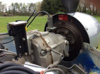
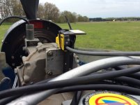
One way to set up the Dyna-Vibe for the 12. This is on a ULS but I have used the same arrangement on the iS.
One way to add trial weights to the spinner:

Calculations then done to place the weight on spinner backplate. Yes you have to drill a hole. Holes in the backplate don't matter much.
BTW, the Dyna-Vibe website includes details specific to the RV-12 prop balancing.
Balancing the RV-12 prop means running the engine so you will not be in the hangar with access to all your tools. So, after some experience running back and forth to get tools and stuff I needed, wasting a lot of time; I made a list and pack a tool caddy to the run-up area. Your list will vary but here is mine.

This is a complex job, be prepared to spend some time researching, and planning; then doing the work. There is a learning curve; good luck!
This is a complex job, be prepared to spend some time researching, and planning; then doing the work. There is a learning curve; good luck!
Last edited:


Nothing wrong with dyna….but the connections on vibrex and micro are better. The battery life on dyna kinda sucks…and in general it’s a good budget balancer.Dyna-Vibe is the only brand that I'm familiar with. What are the advantages of the Vibrex & Micro Vibe?
The others are just more industrial grade. I check often one against the other and sometimes use both, like when tracking my helicopter…it’s nice to cross check and get strobex and vertical and lateral balance all at the same time.
For props, the dyna vibe works fine. The cables are simple plug ins, which you can knock looses getting in and out. Take lots of extra 9 volt batteries and the battery access plate is problematic.
All in all, simple and pretty good.
Last edited:
Dyna-Vibe is the only brand that I'm familiar with. What are the advantages of the Vibrex & Micro Vibe?
ACES also makes a 1015 unit which is somewhere in between the two. It is a little more intuitive, and automatically calculates split weight solutions (lets say it tells you to put 20g at 50 degrees, but you already have holes pre-drilled at 35 and 60 degrees…it will calculate/tell you how much to put at each of the possible points that you enter)
One thing I have not seen mentioned, but perhaps I just missed it, is that the silicone baffle material flopping around can have an impact. I used a bunch of speed tape to keep the baffle rubber in place. Perhaps this is not a problem if you use the very stiff rubber baffle seal material.
Wouldn't it be at 11:20?So let’s say your trigger is set for 12:00 and the run says 5;20 @ .34 IPs…you simply put your prop blade with the tape back pointing to 12:00 and look at a Chadwick chart and if it says add 13grams…you plot 5:20 as the heavy point and add the combined weight of bolt, nut , washer getting as close to 13 grams as possible..@ 11:40
Typo. Yes
I have found that anything predictive or responsive to an algorithm becomes a pain in the butt….just simple clock angle and .ips is quick and easy. Once you start with an algorithm based solution, it becomes a tail chase unless you clear the data each time, the learning program will have you adding weight all over the place,,,ACES also makes a 1015 unit which is somewhere in between the two. It is a little more intuitive, and automatically calculates split weight solutions (lets say it tells you to put 20g at 50 degrees, but you already have holes pre-drilled at 35 and 60 degrees…it will calculate/tell you how much to put at each of the possible points that you enter)
The other thing I forgot to mention is, if you have a choice to add weight vs. remove weights…say from someone else doing a poor job…always remove, first.
As far as splitting weights…I do that all the time. Use the two closest flange screw locations and estimate the amount to split….re-run and look at your move line result…it’s way easier in application that explanation….you are simply adding mass, to resolve a mass Imbalance…use your head and it’s hard to go wrong.
This thread has gone off the rails. This is the RV-12 forum and the OP has asked specific questions on how to use a borrowed DynaVibe. It will be hard for him to separate the wheat from the chaff. All the other comments here about other equipment and methods are probably good info but belong in a different forum and different thread.
A follow up to my earlier post, since I just noticed the borrowed part. I also borrowing the DV unit to balance my prop.
I had to put together the hardware package to mount the sensors on the Rotax. I left that hardware in the balancer kit in a ziplock, along with a printed sheet of those photos and a QR code linking to that dropbox file. The next guy to borrow that unit with a Rotax will have a bit of a shortcut. @BobN54 consider doing the same.
I had to put together the hardware package to mount the sensors on the Rotax. I left that hardware in the balancer kit in a ziplock, along with a printed sheet of those photos and a QR code linking to that dropbox file. The next guy to borrow that unit with a Rotax will have a bit of a shortcut. @BobN54 consider doing the same.
Lots of people seem to make this a complex job, but in reality it is dirt simple. You are correcting a slight mass error. If you knew nothing but a clock angle and .ips…as an exampleBalancing the RV-12 prop means running the engine so you will not be in the hangar with access to all your tools. So, after some experience running back and forth to get tools and stuff I needed, wasting a lot of time; I made a list and pack a tool caddy to the run-up area. Your list will vary but here is mine.
View attachment 114758
This is a complex job, be prepared to spend some time researching, and planning; then doing the work. There is a learning curve; good luck!
Run 1: .4 IPs @6:00. With nothing else…if you took a 10 gram increment and added it close to 12:00 then re-run
Run 2. .30 IPs @ 5:00. Since 10 grams only moved .1 ips…. Let’s add 15 grams @ 11:00
Run 3 .1 IPs @ 5:40. Let’s reduce the 15 grams@11:00 to 10 grams and add the 5 grams we removed, to1 2:00 for a total of 15@ 12:00
Run4: .075 IPs @ 11:50
Anyway…you should see the point. No charts, no nothing…move mass slightly, establish a move line, using small increments, drive the mass imbalance towards the center.Always remember the mass imbalance …expressed as .ips…is the vibration level off balance from center and clock angle is the direction where the mass is heavy.
I don’t want to say anyone can do it…but my 12 year old helps me on props and helicopter tail rotors and he gets it just fine…
One thing that helps is to draw your own polar chart, .ips and clock angles and just focus on the move line in regard to just the four quadrants of 12:00, 3:00, 6:00 and 9:00
Think only about, above the median line of 3&9. Or below…and left or right on 6 and 12.
Drawing the line depicts moving mass in the correct direction.
8:30 and .35…. Is up and to the right. 1:45 and .22 is down and to the left.
My best advice is if you don’t make it complicated…it’s simple, keep it that way.
No….take the spinner off for the runs. It makes virtually no difference. Temporarily attach a screw and washers to the outer flange of the spinner ring. You may need a selection of lengths, to accommodate a stack of washers. USE THE EXISTING SCREW HOLES TO START WITH. You will drill a hole later in the vertical portion of the rear prop bulkhead.
Once you have the appropriate solution, you weight that, you may need two or even three screws and washer stacks initially, but as you resolve, you can usually work down to one, I also use stick on wheel weights, on the inside of the flange for initial.
Once you have a resolved clock angle and approximate weight and are under .1 IPs. It’s pretty easy to game plan where to drill a hole for a 3/16 bolt. On a gram scale, weigh an an3bolt , washer and nut. That’s a baseline solution, the bigger the imbalance, the more washers, hence longer bolt you will need,
It’s pretty intuitive once you start. If you get stuck, feel free to ask questions or reach out directly,
Last edited:
As far as brackets…ANY old chunk of aluminum extrusion works fine. The velocimeter has a 10-32 Allen screw…you can attach that to almost anything, the only thing you don;t want is to have something to floppy,,,so I use 1/8” thick to keep a fairly rigid mount, seldom does it take more than 10 minutes to make a mounting bracket. One tip…you want the cable at the velocimeter secured lightly…meaning not flopping in the prop blast. When I make a mount…I usually allow some excess on the bracket for a hole for a zip tie to secure a small loop of cable to.I really appreciate your replies. Every one is very helpful. I hope we have the right brackets in the kit. Still a bit unsure about the best way to attach temporary weights to the spinner bulkhead flange. I assume the spinner is left on during these runs.
Is the pitot tube not removable? I obviously don’t have a -12…if the spinner has to remain in place, just put longer screw and washer wherever you are adding mass temporarily on the outside of the spinner…use a plastic washer to keep from marring the paint.
I personally would never balance any prop without the spinner on.No….take the spinner off for the runs. It makes virtually no difference. Temporarily attach a screw and washers to the outer flange of the spinner ring. You may need a selection of lengths, to accommodate a stack of washers. USE THE EXISTING SCREW HOLES TO START WITH. You will drill a hole later in the vertical portion of the rear prop bulkhead.
Spinners weigh quite a bit will most definitely affect balance.
Seldom do I see spinners affect overall imbalance by more than a .02-.03 IPs but to each their own. The spinner is so close to the center that it makes virtually no difference.I personally would never balance any prop without the spinner on.
Spinners weigh quite a bit will most definitely affect balance.
Here’s where everyone kicks in with their own technique, and you each has to sort out the wheat from the chaff….if a paying job….meaning getting paid by the hour to perfect someone else’s machine…perhaps…but I have found that once you have a valid resolved clock angle and .ips…and you re-assemble everything for the final balance…you may need one thin washer,,,or thick,,,for final resolution,
Considering that a human…basically cannot feel a vibration at less than .1 and most consider .2 satisfactory…I’ll stand by what I have learned over many years with prop and rotor balancing and tracking…
Last edited:
Just to add another reason I won't do it is I've seen numerous blade fillers broken off or bent from mntc running an engine without the spinner on. Aluminum blade fillers need the support of the spinner to not be ejected by centrifugal force.Seldom do I see spinners affect overall imbalance by more than a .02-.03 IPs but to each their own. The spinner is so close to the center that it makes virtually no difference.
Here’s where everyone kicks in with their own technique, and you each has to sort out the wheat from the chaff….if a paying job….meaning getting paid by the hour to perfect someone else’s machine…perhaps…but I have found that once you have a valid resolved clock angle and .ips…and you re-assemble everything for the final balance…you may need one thin washer,,,or thick,,,for final resolution,
Considering that a human…basically cannot feel a vibration at less than .1 and most consider .2 satisfactory…I’ll stand by what I have learned over many years with prop and rotor balancing and tracking…
You have balance data spinner on and off same prop? Is there an advantage balancing with the spinner off? I've always done it with the spinner on as that is what my final set-up will be and as requested by 3 different Dyna Vibe owners but willing to be taught new tricks.Seldom do I see spinners affect overall imbalance by more than a .02-.03 IPs but to each their own. The spinner is so close to the center that it makes virtually no difference.
The last run I make is final re-assemble…most of the time, the instrument doesn’t even acknowledge a difference from spinner off or on…but I seldom get carried away with things on a prop. Balancing and tracking helicopter is an entirely different thing…
We just received the Dyna-Vibe balancing kit. It is supposedly setup for, and has been used previously, on multiple 912's. The setup differs from what I’ve seen here. Our optical sensor is mounted similarly to Tony_T’s post #6, but on a slightly shorter bracket. More notably, the accelerometer is mounted on the same 4-inch, 1/16" steel bracket right next to the optical sensor, rather than at the front of the gearcase. We did five runs at 5,000 RPM and got 0.00 IPS on four runs and 0.03 IPS on one. Does that sound right? I'm concerned that mounting the accelerometer on a long, thin steel bracket at the back of the gearcase might produce different results than a short, heavy-gauge bracket at the front. Am I overthinking this, or is the bracket flexibility and location likely to skew the data? Our prop is the Van's provided Sensenich 2-blade composite.
Since no reply, I assume you are busy…but mounting the velocimeter on the gearbox wouldn’t be my first look on balance of an engine. While the velocimeter is going to sense and convey an imbalance, the engine block itself is a better source. Anything flexible mount for the velocimeter, will definitely confuse it, since it’s going to see not only accelerations, but also the deceleration from the mount itself.
If you see 5 runs with the same .ips and clock angle…chances are you have a super smooth engine, but typically in my experience, might mean you’re not getting solid results, gear-train would be unlikely to be way off balance, from a manufacturing methods perspective, so the prop, pistons, crank, rods are more typically the sources of imbalances you’re looking to solve for, one blade out of track, will create an imbalance…or a heavy blade etc…
So again, if you have all the same clock angle and .ips results, try moving the mount and seeing if they track properly, meaning if you have a 5.30 clock angle and move the velocimeter back to the engine and it the. Goes to 11:15….then I’d doubt the validity of the results.
Likewise if you get clock angles and put weight on that doesn’t resolve the in some positive direction, I’d doubt the results.
Kinda need more info to make any intelligent assertions.
Walt, appreciate your input. On Lycoming’s I’ve never found this to be an issue, but will look out for it. While the spinner does weigh a bit, from my perspective….more than half its weight is so close to polar center, that I’ve never much found worrying about them to be worthwhile,Just to add another reason I won't do it is I've seen numerous blade fillers broken off or bent from mntc running an engine without the spinner on. Aluminum blade fillers need the support of the spinner to not be ejected by centrifugal force.
What we are typically correcting for is blade imbalance and engine component imbalances…things with more mass and farther from center.
My own O-360 with blended airfoil Hartzell was .29 when I installed the prop. Resolved that down to .029 without spinner and after final assembly it’s .03
It definitely could matter more…but of the ones I’ve seen the spinner is almost undetectable. I’ll be sure to keep an eye on tabs diligently.
You want to mount the accelerometer on the engine, as close to the propeller hub as possible. This puts the sensor closest to the source of imbalance (rotating mass), giving the cleanest signal.We just received the Dyna-Vibe balancing kit. It is supposedly setup for, and has been used previously, on multiple 912's. The setup differs from what I’ve seen here. Our optical sensor is mounted similarly to Tony_T’s post #6, but on a slightly shorter bracket. More notably, the accelerometer is mounted on the same 4-inch, 1/16" steel bracket right next to the optical sensor, rather than at the front of the gearcase. We did five runs at 5,000 RPM and got 0.00 IPS on four runs and 0.03 IPS on one. Does that sound right? I'm concerned that mounting the accelerometer on a long, thin steel bracket at the back of the gearcase might produce different results than a short, heavy-gauge bracket at the front. Am I overthinking this, or is the bracket flexibility and location likely to skew the data? Our prop is the Van's provided Sensenich 2-blade composite.
The accelerometer measures motion in one axis, parallel to the mounting bolt. If it is somewhat flexible, (not floppy), in other directions it is not going to matter.
I agree they are two separate issues. I also agree that 0 IPs is likely a false result. Which is why I asked what the clocking angle is. If clock angle and IPs are same, meaning all clock angles say 12:00 and 0 IPs…. The result is 100% invalid.0 IPS on a Rotax would be next to impossible.
"What we are typically correcting for is blade imbalance and engine component imbalances"
The above is partially correct, prop balancing does not correct engine component imbalance.
Hard to comment much beyond, since no further input from OP
When I did the Dynamic balance on my 12, I left the spinner intact. I drilled a hole in the back plate and tapped it so I could screw in a bolt, washers and nut temporarily to test it. When satisfied, I removed the spinner and mounted the hardware through the hole with the nut securing it properly.
I'll need to make that hardware. Are there specs?A follow up to my earlier post, since I just noticed the borrowed part. I also borrowing the DV unit to balance my prop.
I had to put together the hardware package to mount the sensors on the Rotax. I left that hardware in the balancer kit in a ziplock, along with a printed sheet of those photos and a QR code linking to that dropbox file. The next guy to borrow that unit with a Rotax will have a bit of a shortcut. @BobN54 consider doing the same.
Oh, man, this is good to know. I had visions of taking the spinner on/off/on, with each run.I have done the Dyna Vibe balance on my RV12 without spinner, pitot tube IS removed and have found the spinner makes no difference in IPS on or off plus it's faster to add or remove weights on the back plate.
I'd be willing to place a bet that there is a noticeable difference if I used my machine (MVib II) measuring with/without spinner.I have done the Dyna Vibe balance on my RV12 without spinner, pitot tube IS removed and have found the spinner makes no difference in IPS on or off plus it's faster to add or remove weights on the back plate.
I routinely install weights on bulkheads using #10 bolts/washers down to 1 gram or less (1 thick washer is 1g).
Last edited:
I concur, I have balanced hundreds, the spinner almost always will make a difference. Usually less than .05ips but when you are at the last bit, it matters.I'd be willing to place a bet that there is a noticeable difference if I used my machine (MVib II) measuring with/without spinner.
