I’m working on converting my FP back to CS and while the crank plugs were out I figured I’d give this a try. I was able to see all 6 lobes. This is a narrow deck O360.

Van's Air Force
You are using an out of date browser. It may not display this or other websites correctly.
You should upgrade or use an alternative browser.
You should upgrade or use an alternative browser.
Cam inspection without pulling jugs
- Thread starter Planecrazy232
- Start date

OK - excellent - now how did you do that? What kind of super-pretzel borescope are you using there?
I thought I gave enough hints...
 I used my VA400 through the front of the crankshaft. (it helps to have a hollow crank).
I’m working on converting my FP back to CS and while the crank plugs were out I figured I’d give this a try. I was able to see all 6 lobes. This is a narrow deck O360.
THAT would be worth a magazine article, showing people exactly how to do it! Bravo!!
Paul
Excellent to know that this can be done! I have thought of dropping the oil pan, but there does not seem to be a way to access from there.
I think you can get in if you take the oil pan off, if the scope is small enough, not saying it would be easy though.
OK I was told I needed the $500.00 Vividia because it had a smaller pipe, v/s the $200.00 one So I ordered it.
Pulled the sump off my wide deck 0-0360 c/s prop parallel valve engine.
took a look at the crack and said wow. I used the $200.00 one with ease to reach up to see three front lobes on the cam. Looked good.
so I have an expensive super flexible scope I now no longer have a use for
Sump removal is way less destructive than barrel removal.
Your luck may vary Art
Last edited:
Sump removal is way less destructive than barrel removal.
Your luck may vary Art
Very easy on a fixed pitch without the rear plug in place. Agreed, I wouldn’t remove the plug unless I had a compelling reason to do so, although it’s been done successfully.
I am impressed! I can imagine how one can see w/o the back plug for a few lobes but will need some 3D view of the guts to process how this works.
All these years, all the risk assumed, or barrels removed, to pre-buy the lobes and it is right in front of us all!?!?!
Does this work on all (Lyc) cases and non-solid cranks?
All these years, all the risk assumed, or barrels removed, to pre-buy the lobes and it is right in front of us all!?!?!
Does this work on all (Lyc) cases and non-solid cranks?
I am impressed! I can imagine how one can see w/o the back plug for a few lobes but will need some 3D view of the guts to process how this works.
All these years, all the risk assumed, or barrels removed, to pre-buy the lobes and it is right in front of us all!?!?!
Does this work on all (Lyc) cases and non-solid cranks?
I am struggling to visualize how a scope gets from the forward hollow portion back into the core of the crankcase. It has been a while since I looked at a crankshaft and just cannot get my head around the path.
Hoping the OP will share more detail.
Larry
I am struggling to visualize how a scope gets from the forward hollow portion back into the core of the crankcase. It has been a while since I looked at a crankshaft and just cannot get my head around the path.
Hoping the OP will share more detail.
Larry
Here I am- I wish I took more photos and video during this but I was on a different path at the time...
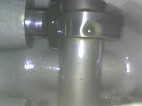
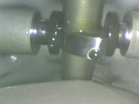
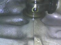
On my hollow crank, the rear plug (about 8" back from the front) looks like a freeze plug. Some of these hollow cranks have a small pipe plug in this location, so I'm not sure if the borescope will go through that small opening. This "freeze plug" was not in place on my engine (set up originally for fixed pitch). So when I pulled the front plug and looked inside past where that rear plug would go, I saw connecting rods. I turned the crankshaft and the rods moved out of the way. That's when I got the borescope idea. The VA-400 borescope is about 20" long and has an articulating head. I inserted the scope and when I got to where the rods were, I articulated the camera head upwards and viola- there was the cam! I then straightened the camera and inserted farther in until the next opening and articulated up again for the next set of lobes. I then went farther back yet (the whole length of the borescope was inside, including the handle stuffed inside the snout of the crank) and was able to see the last set of lobes.
If I ever get the chance to do this again I will certainly document better. Better yet if someone has an engine apart with the case halves open that would be a great tutorial.
Here’s more pictures with and without the rear plug in place. Also the very last lobe. You can see the split of the two rear case halves.
Attachments
Last edited:
Here I am- I wish I took more photos and video during this but I was on a different path at the time...
On my hollow crank, the rear plug (about 8" back from the front) looks like a freeze plug. Some of these hollow cranks have a small pipe plug in this location, so I'm not sure if the borescope will go through that small opening. This "freeze plug" was not in place on my engine (set up originally for fixed pitch). So when I pulled the front plug and looked inside past where that rear plug would go, I saw connecting rods. I turned the crankshaft and the rods moved out of the way. That's when I got the borescope idea. The VA-400 borescope is about 20" long and has an articulating head. I inserted the scope and when I got to where the rods were, I articulated the camera head upwards and viola- there was the cam! I then straightened the camera and inserted farther in until the next opening and articulated up again for the next set of lobes. I then went farther back yet (the whole length of the borescope was inside, including the handle stuffed inside the snout of the crank) and was able to see the last set of lobes.
If I ever get the chance to do this again I will certainly document better. Better yet if someone has an engine apart with the case halves open that would be a great tutorial.
I'm confused!
 But I know this is really interesting, since most people have said that it can't be done.
PilotjohnS
Well Known Member
Design of Crank
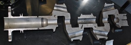
The design of the Lycoming crank has a hole through each main bearing journal. think of the crank as built from a series of tubes. Car engines dont do this, but rather have a solid crank. So if you take a Lycoming crank and look thru the end down the axis, you would see clear thru it, as if it was built from a series of welded tubes (it is not, but same appearance) The center portion of a cylindrical crank journal has little effect on strength, so Lycoming drills them out to save weight.
he just puts a bore scope down the center thru these holes in the main bearing journal. But he also has the ability to turn the end of the flexible bore scope, like a cobra dancing in India, and get the camera closer to the cam lobes.
I'm confused!
View attachment 15060
The design of the Lycoming crank has a hole through each main bearing journal. think of the crank as built from a series of tubes. Car engines dont do this, but rather have a solid crank. So if you take a Lycoming crank and look thru the end down the axis, you would see clear thru it, as if it was built from a series of welded tubes (it is not, but same appearance) The center portion of a cylindrical crank journal has little effect on strength, so Lycoming drills them out to save weight.
he just puts a bore scope down the center thru these holes in the main bearing journal. But he also has the ability to turn the end of the flexible bore scope, like a cobra dancing in India, and get the camera closer to the cam lobes.
Here I am- I wish I took more photos and video during this but I was on a different path at the time...
On my hollow crank, the rear plug (about 8" back from the front) looks like a freeze plug. Some of these hollow cranks have a small pipe plug in this location, so I'm not sure if the borescope will go through that small opening. This "freeze plug" was not in place on my engine (set up originally for fixed pitch). So when I pulled the front plug and looked inside past where that rear plug would go, I saw connecting rods. I turned the crankshaft and the rods moved out of the way. That's when I got the borescope idea. The VA-400 borescope is about 20" long and has an articulating head. I inserted the scope and when I got to where the rods were, I articulated the camera head upwards and viola- there was the cam! I then straightened the camera and inserted farther in until the next opening and articulated up again for the next set of lobes. I then went farther back yet (the whole length of the borescope was inside, including the handle stuffed inside the snout of the crank) and was able to see the last set of lobes.
If I ever get the chance to do this again I will certainly document better. Better yet if someone has an engine apart with the case halves open that would be a great tutorial.
Here’s more pictures with and without the rear plug in place. Also the very last lobe. You can see the split of the two rear case halves.
Thanks! I get it now. I wasn't thinking about the offset right behind the forward journal. Makes sense that there is a large hole there, allowing a borescope into the guts.
Very clever.
Pilot8
Well Known Member
This video has a good camera angle to visualize how the borescope was routed:
https://www.youtube.com/watch?v=_49xL9oFLa8
https://www.youtube.com/watch?v=_49xL9oFLa8
Last edited:
This video has a good camera angle to visualize how the borescope was routed:
https://www.youtube.com/watch?v=_49xL9oFLa8
Thanks Sam - that was very helpful!

One more question - - -sorry
This cross section is good for the inspection understanding, but the mains have a drilled passage that feeds oil to the rods. This is typically fed with a center groove in the bearing. With lightening holes, the cross drilled passage can be at an angle to miss the lightening hole, but there in the center main bearing is a pesky hole into the lightening bore. What's that?? Some designs use a plug in there to allow oil distribution by sealing the bore, which is fine, but the design of it matters. It could be a dog-bone sleeve pressed in allowing the borescope to pass. Can anyone confirm that aspect of this design? Rocketbob?
Removing the prop, and maybe the crankshaft plug, will require a couple of hours work... but the idea is absolutely brilliant
And far better than pulling jugs or the oil pan...
PS
Never too old to learn
This cross section is good for the inspection understanding, but the mains have a drilled passage that feeds oil to the rods. This is typically fed with a center groove in the bearing. With lightening holes, the cross drilled passage can be at an angle to miss the lightening hole, but there in the center main bearing is a pesky hole into the lightening bore. What's that?? Some designs use a plug in there to allow oil distribution by sealing the bore, which is fine, but the design of it matters. It could be a dog-bone sleeve pressed in allowing the borescope to pass. Can anyone confirm that aspect of this design? Rocketbob?
Last edited:
rocketbob
Well Known Member
Using this method one can't get a good look at tappet faces so its of very limited usefulness. Pulling the spinner and prop and plug, getting a new plug and installing it is more work than pulling a cylinder.
On a 540 one can get a camera down the dipstick hole to look at the middle lobes.
On a 540 one can get a camera down the dipstick hole to look at the middle lobes.
This cross section is good for the inspection understanding, but the mains have a drilled passage that feeds oil to the rods. This is typically fed with a center groove in the bearing. With lightening holes, the cross drilled passage can be at an angle to miss the lightening hole, but there in the center main bearing is a pesky hole into the lightening bore. What's that?? Some designs use a plug in there to allow oil distribution by sealing the bore, which is fine, but the design of it matters. It could be a dog-bone sleeve pressed in allowing the borescope to pass. Can anyone confirm that aspect of this design? Rocketbob?
I noticed that as well. That is a pretty big bore and can't imagine that it is left open. I assumed there must be some kind of covers for that lightening bore.
Larry
Using this method one can't get a good look at tappet faces so its of very limited usefulness. Pulling the spinner and prop and plug, getting a new plug and installing it is more work than pulling a cylinder.
with all due respect Bob, kindly allow me to partly disagree...
Swiss story:
Many moons ago, we had an accident, 3 people lost their lives following a crash that occurred in the initial climb. The enquiry board cited partial power delivered by the engine due to badly worn cams as one of the causes, the report, in English language: https://www.sust.admin.ch/inhalte/AV-berichte/2160_e.pdf
As a follow-up, the Swiss FOCA (Fed Office for Civil Aviation) implemented TBO as rule making, e.g. the recommendation of 12 years became a mandatory engine overhaul. Unless you provided the authority with an additional maintenance program, and a one time (repetitive in fact, since it was supposed to be done every 6 years) inspection of the camshaft. This was done by pulling 2 cylinders, and, using a mirror, inspect the cams.
I owned a Falco at the time, and the removal of the cowl, the baffles, relevant ignition leads and spark plugs, pulling and reinstalling the jugs, took the better part of 2 days. With all the associated risks, as detailed many times by Mike Busch.
Removing and installing spinner/prop and eventually the plug, could probably be achieved in 1/2 day or less, and with less risks. As you state, an inspection of the tappet faces seems difficult.
Swiss story epilogue: hundreds of engines were inspected. AFAIK, only a handful were found with a damaged crankshaft, and this lead to the FOCA to drop the one time inspection.
Just surprised that nobody ever mentioned this method of inspection at the time, and I for one wasn't aware of it until this thread came into being.
i found that swiss report about the fatal accident very interesting.
i understand long sitting airplane ==> rusting cam lobes ==> more wear/grinded down lobes ==> valves don't open completely anymore ==> loss of power ==> crash.
what i don't get is that it seems to happened so rapidly. one should think that the process of corroding and grinding of the cam lobes should take some time. at least long enough that the pilot/owner of the aircraft does notice that something's wrong with the engine. reduction of power and (if the lobes aren't grinded down evenly) it should shake like crazy.
anyone with a explanation? does it happen really so fast?
with all due respect Bob, kindly allow me to partly disagree...
Swiss story:
Many moons ago, we had an accident, 3 people lost their lives following a crash that occurred in the initial climb. The enquiry board cited partial power delivered by the engine due to badly worn cams as one of the causes, the report, in English language: https://www.sust.admin.ch/inhalte/AV-berichte/2160_e.pdf
As a follow-up, the Swiss FOCA (Fed Office for Civil Aviation) implemented TBO as rule making, e.g. the recommendation of 12 years became a mandatory engine overhaul. Unless you provided the authority with an additional maintenance program, and a one time (repetitive in fact, since it was supposed to be done every 6 years) inspection of the camshaft. This was done by pulling 2 cylinders, and, using a mirror, inspect the cams.
I owned a Falco at the time, and the removal of the cowl, the baffles, relevant ignition leads and spark plugs, pulling and reinstalling the jugs, took the better part of 2 days. With all the associated risks, as detailed many times by Mike Busch.
Removing and installing spinner/prop and eventually the plug, could probably be achieved in 1/2 day or less, and with less risks. As you state, an inspection of the tappet faces seems difficult.
Swiss story epilogue: hundreds of engines were inspected. AFAIK, only a handful were found with a damaged crankshaft, and this lead to the FOCA to drop the one time inspection.
Just surprised that nobody ever mentioned this method of inspection at the time, and I for one wasn't aware of it until this thread came into being.
Last edited:
Mickey,I'm confused!
View attachment 15060
You have probably already figured it out, thanks to Dan's nice photo. Hopefully this drawing will also help. This will only work if:
1 You have a hollow crankshaft
2 You have a fixed pitch propeller without the CS oil return tube to the rear mounted governor adapter. [rear plug has been removed]
You need to remove the prop and the crankshaft front plug for access. You need to install a new front plug when finished, then re-install the prop. See below. Those who succeed should earn an honorary degree in arthroscopic surgery.
")

Last edited:
Radioflyer
Well Known Member
…..On a 540 one can get a camera down the dipstick hole to look at the middle lobes.
[/QUOTE]
Right, I have heard of this. I haven’t had a chance to do this myself, but was of the impression that this could be done even on an O-320/360.
[/QUOTE]
Right, I have heard of this. I haven’t had a chance to do this myself, but was of the impression that this could be done even on an O-320/360.
[/QUOTE]Right, I have heard of this. I haven’t had a chance to do this myself, but was of the impression that this could be done even on an O-320/360. [/END QUOTE]…..On a 540 one can get a camera down the dipstick hole to look at the middle lobes.
I have not tried it on a 320 or 360 [non 76 series engines]. The dipstick tube mounts to the rear of the right hand crankcase half, above the sump. You would probably want to lower or drain the oil first, so as not to risk ruining the borescope by submerging it in oil.
You could only view the back half of the camshaft/lifters. The back half of the crankcases [at the bottom] are open to the sump. Rotating the crankshaft to get the connecting rods out of the way would be necessary, I suspect. However, the front half of the crankcases join together. That and the center bearing would block access to the front half of the engine. For a "pre buy" this is better than nothing, and looks like it would be relatively easy.
Last edited:
On a Superior engine case with roller lifters, you can pull each individual lifter out and inspect the cam and the lifter.
The 76 series Lycomings also have "barrel" style valve lifters which can be removed without cylinder removal for viewing.On a Superior engine case with roller lifters, you can pull each individual lifter out and inspect the cam and the lifter.
Charlie
Per my post #27, your borescope would need to have a very thin [5-6mm diameter] cable and camera. It would have to be able to bend the cable nearly 180 degrees to fit through the small gap at the crankcase mating line above the sump. Unless your scope has a really long cable, you would also probably need to remove the dipstick tube.
Charlie
Charlie
sansoneservices
Well Known Member
I'm afraid the scope could get irretrievable requiring teardown. This is a great thread but I still will pull the jug. Properly done there is little risk.
For the process of going in through the front of the hollow crank, bear in mind that angle-valve engines don't use a freeze plug to plug the back of the hollow bore of the crank as parallel-valve engines do. Instead, there is a restricted area with a pipe plug threaded into it. The pipe plug has an "Allen" head for wrenching. But there is also the oil cross tube bridging across the hollow bore. You must be very careful not to damage that cross tube while trying to remove the pipe plug. A ball driver may help, but then the problem is that the pipe plug is very tight and takes a lot of wrenching torque to loosen it. Perhaps more than a ball driver can deliver. In my case, that plug was so tight I could not turn it, and I did not want to risk damaging the oil cross tube, so I gave up and left it be.
Steve, you haven't read the entire thread. Reread my post #27. The method mentioned won't work on ANY CS prop crankshaft.For the process of going in through the front of the hollow crank, bear in mind that angle-valve engines don't use a freeze plug to plug the back of the hollow bore of the crank as parallel-valve engines do. Instead, there is a restricted area with a pipe plug threaded into it. The pipe plug has an "Allen" head for wrenching. But there is also the oil cross tube bridging across the hollow bore. You must be very careful not to damage that cross tube while trying to remove the pipe plug. A ball driver may help, but then the problem is that the pipe plug is very tight and takes a lot of wrenching torque to loosen it. Perhaps more than a ball driver can deliver. In my case, that plug was so tight I could not turn it, and I did not want to risk damaging the oil cross tube, so I gave up and left it be.
I agree. To inspect the cam/lifters on your own machine or that of a buddy. For a pre-buy inspection, the owner may not let you do that. If the scope did get stuck, you would have to pull the intake tubes and the sump. I was merely pointing out that while it "may" be doable, it will be tricky.I'm afraid the scope could get irretrievable requiring tear down. This is a great thread but I still will pull the jug. Properly done there is little risk.
I don't see why it wouldn't work for a CS prop crankshaft, assuming you can get the pipe plug out, and the borescope head is smaller than the pipe thread. You could surely snake the borescope around the oil drain tube. It just requires a lot of care to get the plug out.Steve, you haven't read the entire thread. Reread my post #27. The method mentioned won't work on ANY CS prop crankshaft.
I am not sure there is a lot of value in doing that during a prebuy. This typically starts with very light corrosion on the lifter base that you would never see with a borescope. You would only catch it in later stages and these later stages move pretty fast. If the lobe is already worn away, you are probably better off putting a dial indicator on the rocker arm, looking for reduced lift. If in the early stages, you run the risk of missing the corrosion and telling the buyer all is good, only to lose the lobe 50 hours later. Currently a long thread on that very subject.I agree. To inspect the cam/lifters on your own machine or that of a buddy. For a pre-buy inspection, the owner may not let you do that. If the scope did get stuck, you would have to pull the intake tubes and the sump. I was merely pointing out that while it "may" be doable, it will be tricky.
My feelings are there is no point looking for it, as there is no way to stop it, once it has started. Better to religiously examine filter contents.
Norman CYYJ
Well Known Member
I, for one would never let somebody go that deep into an engine for a prebuy. I have seen too many prebuys that were done and very sloppily put back together.I am not sure there is a lot of value in doing that during a prebuy. This typically starts with very light corrosion on the lifter base that you would never see with a borescope. You would only catch it in later stages and these later stages move pretty fast. If the lobe is already worn away, you are probably better off putting a dial indicator on the rocker arm, looking for reduced lift. If in the early stages, you run the risk of missing the corrosion and telling the buyer all is good, only to lose the lobe 50 hours later. Currently a long thread on that very subject.
My feelings are there is no point looking for it, as there is no way to stop it, once it has started. Better to religiously examine filter contents.
You wouldn’t let an inspector pull a rocker cover? I would fully expect pushback on pulling a cylinder as that is pretty invasive., but pulling a rocker cover is literally two minutes, assuming rubber gaskets. I don’t do any of this during a prebuy, but i do do warn buyers about sellers that won’t let you do things like pull plags for borescope and compression. I don’t think you can easily sell a plane without allowing this kind of inspectionI, for one would never let somebody go that deep into an engine for a prebuy. I have seen too many prebuys that were done and very sloppily put back together.
Can you measure cam lift on an engine with hydraulic lifters?I am not sure there is a lot of value in doing that during a prebuy. This typically starts with very light corrosion on the lifter base that you would never see with a borescope. You would only catch it in later stages and these later stages move pretty fast. If the lobe is already worn away, you are probably better off putting a dial indicator on the rocker arm, looking for reduced lift. If in the early stages, you run the risk of missing the corrosion and telling the buyer all is good, only to lose the lobe 50 hours later. Currently a long thread on that very subject.
My feelings are there is no point looking for it, as there is no way to stop it, once it has started. Better to religiously examine filter contents.
Typically the lifter plunger will hold the pressure for the test at zero lash, but that is not universal. On the upside, you can’t get a false positive, only a false negative. If all 8 are in spec, you can say all lobes are in spec. If one reads low, you don’t know if the lobe is worn down or the plunger collapsed. In that case, you remove the plunger and replace the pushrod with a rod that is retained by a spring and measure that. These are all quickly ideas for a prebuy. If i was doing a formal test for myself, I would pull the rockers, rods and plungers. Then make a rod that goes into the lifter base and has a spring attached to head to keep it tensioned. Then put the indicator on the rod. This way you don’t have to deal with rocker ratios. You are directly measuring cam lift.Can you measure cam lift on an engine with hydraulic lifters?
Loosely, if your lifters are not clattering at startup, they have tight enough clearance to hold zero lash at shut down.
To be clear, by the time you can measure a reduced lift, the issue should have already been apparent in your filter analysis. Now magic bullet here to catch this early, though it is a good way to confirm that lifter spalling is the source of the filter metal.
Last edited:
Norman CYYJ
Well Known Member
Doing a compression test is one thing, but opening up any part of the engine not a chance.Typically the lifter plunger will hold the pressure for the test at zero lash, but that is not universal. On the upside, you can’t get a false positive, only a false negative. If all 8 are in spec, you can say all lobes are in spec. If one reads low, you don’t know if the lobe is worn down or the plunger collapsed. In that case, you remove the plunger and replace the pushrod with a rod that is retained by a spring and measure that. These are all quickly ideas for a prebuy. If i was doing a formal test for myself, I would pull the rockers, rods and plungers. Then make a rod that goes into the lifter base and has a spring attached to head to keep it tensioned. Then put the indicator on the rod. This way you don’t have to deal with rocker ratios. You are directly measuring cam lift.
Loosely, if your lifters are not clattering at startup, they have tight enough clearance to hold zero lash at shut down.
To be clear, by the time you can measure a reduced lift, the issue should have already been apparent in your filter analysis. Now magic bullet here to catch this early, though it is a good way to confirm that lifter spalling is the source of the filter metal.
I would say that while your suggestion is "possible", it would be as or more difficult that checking via the dipstick tube. The issue won't be removing that plug, it will be reinstalling it. Myself, IF I considered doing this, I would want to try these approaches on an engine out of the plane with the sump removed, first. For your suggestion, a red tagged angle valve crankshaft out of the engine. Hmm, maybe I'll take a run down to Certified Engines and see what is in their scrap pile? Emmm, maybe not!I don't see why it wouldn't work for a CS prop crankshaft, assuming you can get the pipe plug out, and the borescope head is smaller than the pipe thread. You could surely snake the borescope around the oil drain tube. It just requires a lot of care to get the plug out.

No way can you get a view of the camshaft from the dipstick hole on a 4 cyl lycoming. However, if you take the fuel pump off, 2 bolts, you can put a scope down that hole and all the way inside the crankcase. That also applies to a 6 cylinder. Getting a really good view of the cam and tappets will be difficult but you should be able to see if the tappet faces are shiny nor not, which is the important bit.
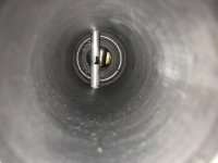
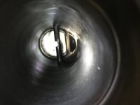
Here's a video of me scoping my O320 when I converted it to constant speed. Before I put the rear plug in I fed a scope down inside. I put a plastic bag in the crankshaft so I didn't cover the borescope in oil, so it looks a little strange to start with... Interestingly, the tappet faces are showing the beginnings of spalling, yet when I tore the engine down 200hrs later they looked identical with no signs of further deterioration on the cam or tappets.
Here's a video of me scoping my O320 when I converted it to constant speed. Before I put the rear plug in I fed a scope down inside. I put a plastic bag in the crankshaft so I didn't cover the borescope in oil, so it looks a little strange to start with... Interestingly, the tappet faces are showing the beginnings of spalling, yet when I tore the engine down 200hrs later they looked identical with no signs of further deterioration on the cam or tappets.
A good point here. Because this is rarely done, we have limited info on what might be considered acceptable wear, that will never progress to worn lobes and that which will continue to progress. If you already have a serious spalling problem, measuring valve lift will confirm it.. this example teaches us that not all non perfect surfaces lead to worn lobes. I suspect many that saw what 390 did would assume it was inevitable and start a tear down. An interesting tale of caution for those considering doing this. Kind of like finding metal in the filter. Is it just the byproduct of a normal engine or the signs of something wearing away. Not always an easy call for someone who hasn’t seen 100’s of examples with access to the ultimate condition.... Interestingly, the tappet faces are showing the beginnings of spalling, yet when I tore the engine down 200hrs later they looked identical with no signs of further deterioration on the cam or tappets.
Yeah, I was expecting it to be totally ruined by the time I tore the engine down.
Here are some close ups of what I removed.
This lifter face feels mostly smooth but you can see areas where pitting has occurred, so eventually this is going to get really bad, but I find it interesting that it operated in this condition for so long. Same for the cam, no actual wear on the cam lobes but quite serious pitting.
(These parts are pretty dusty because they've been sat in the corner for a few months)


That lifter looks like someone previously "rejuvenated" it via die grinder with grinding pad. Notice the arc pattern. You can also kind of make out the jagged center area where the case hardening is ground away (light center vs darker perimeter).
These were new Superior tappet bodies at overhaul back in 2002. At least that's what the invoice says! I should have mentioned that these were covered in oil to preserve them on removal, but I'd wiped over the face with my thumb prior to taking the photo so that's the reason for this arc pattern.
I believe the base have a concave shape, to induce rotation, and thought the shape was ground into the base, then case hardened. So seeing grinding marks is normal or used to be normal if now done via cnc, but i bet they are still ground.That lifter looks like someone previously "rejuvenated" it via die grinder with grinding pad. Notice the arc pattern. You can also kind of make out the jagged center area where the case hardening is ground away (light center vs darker perimeter).
View attachment 88721
View attachment 88722
