

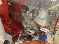
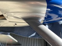
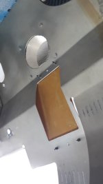
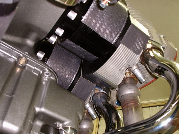
I went with a mini-duct per a later DanH post ..it was easy to make and gives more cross sectional area for the air to get through. YMMV, but my #3 has no cooling issues. I did a similar thing on the front of #2, tucked behind the IO-360 snorkel. The only cooling mod I had to do after break-in was to remove the dam in front of #1.
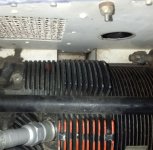
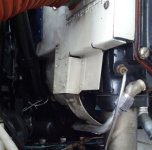
(photos prior to sealing with RTV)
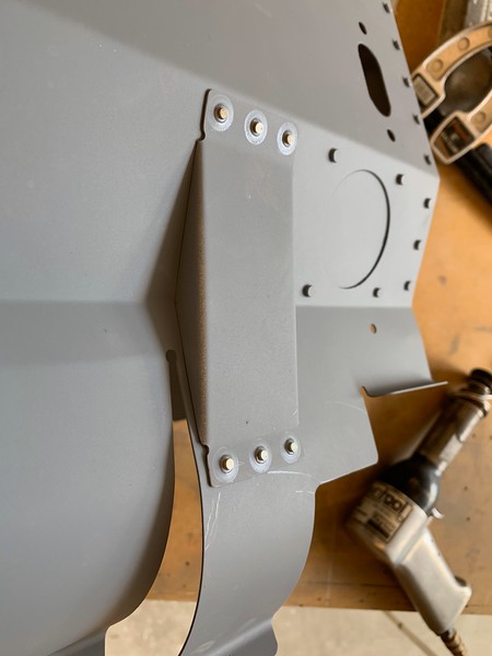
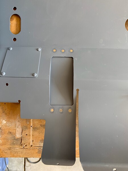
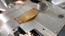
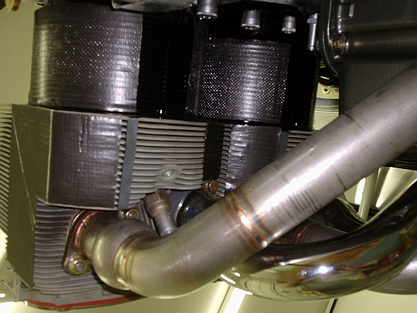
(photos prior to sealing with RTV)


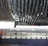
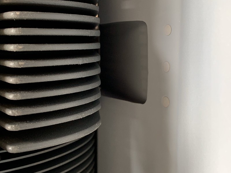
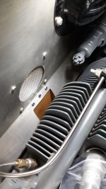
 ). Not rocket science but on warm days my #3 gets hot on climbout like with a lot of us here, every little bit helps.


")


