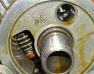
I am having a really hard time wrapping my head around how that internal filter element got crushed/twisted by oil pressure - I think we need one of Dan’s cross-section illustrations to see where the crushing pressure is coming from and where it is deadheading against.
One outlier here is the use of a transmission filter. In this case the 51624 is a design specific to a Powershift transmission in a Hyster forklift. The Powershift is a pedal operated hydrostatic with a rapid forward-reverse function. The fluid used is J20 (now J20C), a widely used John Deere spec.
The viscosity of J20 is around 60 cSt @ 40C, and 9.5 cSt @ 100C. As previously noted, the viscosity of Phillips 20W-50 is 159 cSt @ 40C, and 19.8 cSt @ 100C. The aviation oil is almost 3x thicker at 40C and about twice as thick at 100C. 40C is 104F. Given a cold crank at say 7C (45F), Phillips 20W-50 could be 4x or 5x thicker than the fluid typically used with the 51624.
Wix lists the 51624 as 19 micron nominal, and does not assign a dual beta as they do with their engine oil filters, which typically have nominal ratings between 20 and 25. There is no information specifically relating flow restriction to nominal ratings, but they do suggest the 51624 is more restrictive than a motor oil filter. That could be checked with a simple gravity flow test, an elevated bucket feeding a tee, which in turn feeds two comparison filters. Put a catch can under each filter, fill the bucket, and come back in a hour.
For the moment, assume the media is overly restrictive for the oil in use, a cold start was performed, the canister was subjected to a significant deltaP, and the bypass valve couldn't keep up, i.e. maintain deltaP below its rated max of 19 psi. What happens?
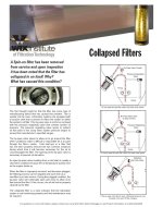
A few readers doubt a simple deltaP overpressure could bend the end caps. Actually it becomes more and more likely to bend the end caps as the ratio of diameter to height is increased. Shorter, fatter filters will result in higher rate of bent end caps.
Think of the filter cartridge as a balloon. Pressure is equal on all sides. When the media begins to collapse inward, there are two forces available to bend the caps. One is the pressure on the outside, and the other is due to the media pulling the perimeter.

The net is full of collapse photos.

Notice the
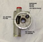
green arrow in the diagram above? There is one unbalanced pressure pushing the canister down against its base. The force would be equal to the area of the bypass valve base times the fluid pressure in psi. Here the valve base is about 1" D, so area is 0.785 sq in. If (picking a number for example) deltaP rose to 20 psi, just one more than the rated maximum, the resulting force would push down on the bypass valve with 15.7 lbs. If it bends the flat section with the holes, the bypass flow area is decreased. The deltaP immediately rises further, and the valve bends a little more. The process doesn't stop until the system reaches equilibrium....which is where Steve found his. Again, a little test would be illustrative. Put a new valve on a flat surface and load it with weight until it starts to bend.
(A) valve
(B) deltaP below opening pressure, valve closed
(C) deltaP well above opening pressure, valve open to maximum.
(D) bent inlet disk reduces flow area


") ), they are based on the Poiseuille equation for laminar flow through cylindrical passages. The equation is more accurate for longer holes, lower flow rates, and higher viscosity. The very short holes are outside its range of applicability at higher flow rates and lower viscosities, but the numbers will give a rough indication for comparison.
), they are based on the Poiseuille equation for laminar flow through cylindrical passages. The equation is more accurate for longer holes, lower flow rates, and higher viscosity. The very short holes are outside its range of applicability at higher flow rates and lower viscosities, but the numbers will give a rough indication for comparison.
 .
.


