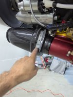
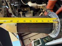
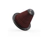
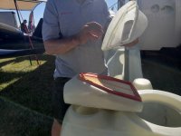
Curious what others have for a air intake, filter, setup on their Rockets. After First flight it turned the belly Black. After conversation with Airflow Performance some checks and pics sent it was suggested try a flight without the air filter in the current housing. Don was right that cleaned it up and leaned it out. Now to find a setup that can flow twice as much air. Curious want others are using and what they made work and what didn't work. If you had to rejet to get to work. Pics are worth 1000 words. Thanks in advance. Pic is my current failed setup.

Van's Air Force
You are using an out of date browser. It may not display this or other websites correctly.
You should upgrade or use an alternative browser.
You should upgrade or use an alternative browser.
Rocket Airfilter
- Thread starter Little Al
- Start date

Toobuilder
Well Known Member
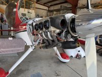
I'm running SDS EFI so the throttle body is nothing more than an air valve - no worry about bugs or debris clogging up the works. My air filter is in the plenum behind the TB - and it's a big one. No discernable MAP loss with this filter. I have a buddy with Bendix injection that's going to try this setup, but so far has not flown. I have 400+ hours on mine.
I recognize this solution is pretty far off the reservation, but maybe will give some ideas.

I recognize this solution is pretty far off the reservation, but maybe will give some ideas.
If you have horizontal induction, check out our ram-air intakes at HP-Aircraft.comCurious what others have for a air intake, filter, setup on their Rockets. After First flight it turned the belly Black. After conversation with Airflow Performance some checks and pics sent it was suggested try a flight without the air filter in the current housing. Don was right that cleaned it up and leaned it out. Now to find a setup that can flow twice as much air. Curious want others are using and what they made work and what didn't work. If you had to rejet to get to work. Pics are worth 1000 words. Thanks in advance. Pic is my current failed setup.
My air filter is in the plenum behind the TB - and it's a big one. No discernable MAP loss with this filter.
View attachment 104475
Mike, that is very clever! Me like.
Curious what others have for a air intake, filter, setup on their Rockets. After First flight it turned the belly Black. After conversation with Airflow Performance some checks and pics sent it was suggested try a flight without the air filter in the current housing. Don was right that cleaned it up and leaned it out. Now to find a setup that can flow twice as much air. Curious want others are using and what they made work and what didn't work. If you had to rejet to get to work. Pics are worth 1000 words. Thanks in advance. Pic is my current failed setup.
Typical for the smaller cone filters. I did one with a large cone a year or so back. Worked great, but the manufacturer dropped the filter from production (grrr...).
Best bet is a flat plate filter, because they have full depth pleats (generally 7/8" to 1") across the entire face area, which means a lot more media area.
Email sent I really like that setupIf you have horizontal induction, check out our ram-air intakes at HP-Aircraft.com
I like it alot. It does help give ideas. Like the motor mount heats shields too.I'm running SDS EFI so the throttle body is nothing more than an air valve - no worry about bugs or debris clogging up the works. My air filter is in the plenum behind the TB - and it's a big one. No discernable MAP loss with this filter. I have a buddy with Bendix injection that's going to try this setup, but so far has not flown. I have 400+ hours on mine.
I recognize this solution is pretty far off the reservation, but maybe will give some ideas.
View attachment 104475
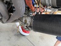
Note also the exhaust extractor/ejectorsEmail sent I really like that setup
I like it alot. It does help give ideas. Like the motor mount heats shields too.
I did notice the what I would call velocity stacks around the exhaust pipes. Im guessing that acts like a venturi to accelerate the cooling air coming out. I may have to build upon that idea depending how my setup works
Attachments
Toobuilder
Well Known Member
I did notice the what I would call velocity stacks around the exhaust pipes. Im guessing that acts like a venturi to accelerate the cooling air coming out. I may have to build upon that idea depending how my setup works
The Most Elaborate Cowl Flap Systems = Show Us Let's Discuss.
I started a thread "Servos for Carb Heat and or Alternate Air". The question was using servos or linear actuators to move the carb heat door in a Van's FAB. I am unlikely to do that, will likely use a Teleflex push pull control cable, but in the process talented and creative builders have come...
vansairforce.net
Another option.
May I ask the make and number of that filter?
Break.
I did this can for a buddy, then the manufacturer stopped making the big cone filter element. It worked well, because it packaged a lot of media area.


Dan,May I ask the make and number of that filter?
Break.
I did this can for a buddy, then the manufacturer stopped making the big cone filter element. It worked well, because it packaged a lot of media area.
View attachment 104548
View attachment 104551
This is what I want!
Did you have an alternate air capability as well?
Carl
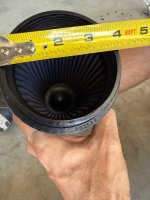
I don’t know the make and model of the filter. In one of the pictures it shows “E035A4” but a basic google search did not return anything. The plane is new to me and I am currently trying to find another filter for the shelf. Rumor is Dave Anders had a hand in the design/construction as he was next door neighbor to the builder. Builder is not available for questions. There is no alternate air provision.May I ask the make and number of that filter?
Break.
andoman
Well Known Member
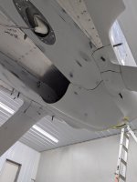
My HRII has the p-51 smile.
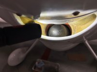
Similar to Dan’s post #11 above except in 2 pieces. The front piece is the smile mounted to the cowl. The aft piece is mounted to the servo. The pieces are connected by a short piece of 6” dia. sceet.
The cone filter is just like the one pictured above except it has a flange in the back instead of the ring that attaches to a tube.
I believe this setup was designed and sold by Sam James. I had to modify it a bit to make it work.
Sorry, I don’t have a pix of the aft attachment to the servo half. But here is a shot looking down the intake:
Attachments
What filter are you using?My HRII has the p-51 smile.
Similar to Dan’s post #11 above except in 2 pieces. The front piece is the smile mounted to the cowl. The aft piece is mounted to the servo. The pieces are connected by a short piece of 6” dia. sceet.
The cone filter is just like the one pictured above except it has a flange in the back instead of the ring that attaches to a tube.
I believe this setup was designed and sold by Sam James. I had to modify it a bit to make it work.
Sorry, I don’t have a pix of the aft attachment to the servo half. But here is a shot looking down the intake:
Did you ever measure the amount of ram air boost you are getting?
Carl
andoman
Well Known Member
Sorry, Carl, I don’t have the number. I just had it out last week to clean and reoil during my CI and was going to write down the no. but I forgot to. 
I think I’m down at least .5” MAP over pure ram. I also think that a larger protruding scoop (ala F1) is more efficient. My “tucked up tight behind the spinner with the flush top lip” opening doesn’t scream “ram.” It does look good, though!
I hope K&N still makes my filter.
It looks like this but I think mine is longer:
Attachments
K & N - RU-3130I don’t know the make and model of the filter. In one of the pictures it shows “E035A4” but a basic google search did not return anything. The plane is new to me and I am currently trying to find another filter for the shelf. Rumor is Dave Anders had a hand in the design/construction as he was next door neighbor to the builder. Builder is not available for questions. There is no alternate air provision.
Thanks for the feed.Sorry, Carl, I don’t have the number. I just had it out last week to clean and reoil during my CI and was going to write down the no. but I forgot to.
I think I’m down at least .5” MAP over pure ram. I also think that a larger protruding scoop (ala F1) is more efficient. My “tucked up tight behind the spinner with the flush top lip” opening doesn’t scream “ram.” It does look good, though!
I hope K&N still makes my filter.
It looks like this but I think mine is longer:
Averaging through several data samples after I calibrated my MP indication I have 0.4” of boost using the standard Van’s snorkel on my RV-8. The new RV-10 will sport a Cold Air Sump IO-540. The air filter setup is becoming challenging - I’m hoping to get at least the same 0.4” of boost.
The K&N site says I need ~70 sq-in of air filter for the IO-540 @2700 RPM.
Carl
Registering all the available dynamic pressure requires bringing the flow to a complete halt...like a pitot, a closed end system. It doesn't happen here, because a combustion air intake does not bring the flow to a halt. Any ram rise is a function of how much the flow is slowed, but it never stops.
Also recall dynamic pressure = 1/2 density * velocity squared. There is no single value, It is a function of both altitude and airspeed.
Best I can tell, picking up dynamic pressure (ram) is pretty easy. The real gains are found in reducing induction system loss.
Incorporate enough filter media area and pressure drop across the filter is tiny, like 3" H2O. From there it's about the throttle body and induction tract of the engine. The best numbers I've seen were from an aircraft with a Sky Dynamics taper tube manifold. On the other hand, the VE for the legacy Lyc horizontal system appears to be about 0.875, meaning there is a lot of room for improvement.
The equations on the FAQ page? ? They don't consider the pleat depth. What counts is not based on the surface area of the physical shape, but rather on the area of the media if cut from the filter and spread out. The tapered filters tend to have very shallow pleats at the small end. Even the cylindrical filters tend to be shallow compared to the big flat plate filters, as the plate filters generally have pleats between 7/8' and 1' deep.The K&N site says I need ~70 sq-in of air filter for the IO-540 @2700 RPM.
Last edited:
Dan,The equations on the FAQ page? ? They don't consider the pleat depth. What counts is not based on the surface area of the physical shape, but rather on the area of the media if cut from the filter and spread out. The tapered filters tend to have very shallow pleats at the small end. Even the cylindrical filters tend to be shallow compared to the big flat plate filters, as the plate filters generally have pleats between 7/8' and 1' deep.
I fully agree. That equation is a gross estimate at best. I’m just struggling to find a practical approach to avoid using an under sized filter. Thus the reason for my question on what the IO-540 Rocket crowd is using for a filter.
The cone filter and housing that came from James Cowl seems too small for a Cold Air Sump IO-540. I’m using a modified James Cowl made for a cold air sump RV-10.
I want to avoid the “ram air or filter” selection approach.
Carl
andoman
Well Known Member
Found my filter no.:
K&N E-0995. It fits a stock 4.0L Ford Explorer.
A.I. math says the following:
-the Explorer redlines at 6000 rpm. At 85% VE that’s 360 CFM of air.
-at the same VE, the 540 Lyc at 2700 rpm pumps 357 CFM of air.
I therefore proclaim my K&N cone unit to be as satisfactory in my plane as it is in the truck it was designed for.
No doubt there are gains to be had with a larger filter, but I’m so glad I will now loose no sleep over that fact! ;-)
Hey Dan and Carl,Dan,
I fully agree. That equation is a gross estimate at best. I’m just struggling to find a practical approach to avoid using an under sized filter. Thus the reason for my question on what the IO-540 Rocket crowd is using for a filter.
The cone filter and housing that came from James Cowl seems too small for a Cold Air Sump IO-540. I’m using a modified James Cowl made for a cold air sump RV-10.
I want to avoid the “ram air or filter” selection approach.
Carl
Data is a good thing!
Until recently, James aircraft was still advertising the MkIV Air filter assembly for IO-540's up to 300HP. I unfortunately purchased 2 of these units.
Talking at length with Rob Heap (Ex-Engineer at Van's Aircraft ) who solved the RV-14 EXP intake solution, he recommended getting it tested by Don at Air Flow Performance.
So I boxed up and sent from Australia 2 x assembled MkIV Air filter assemblies and a FM-300R FCU and a SDS 90mm Throttle Body for testing.
The results where abysmal !
The Mk-IV Air Filter Assembly is exactly 50 % too small for the IO-540!
The Alternate Air Design of the MK-IV will not run an IO-540 with out extreme surging and richness on the FM300R, it may run on the SDS EMF-6EFII as it has the ability to adjust rapidly but is massively undersized for the IO-540.
The Conical Filter is massively undersized to run the IO-540
Extracts from Don's Testing are as follows,


These were both modified MkIV's with 4" intakes.

Don tested both air filter assemblies with and with and without air-filters and also tested the comparison between the SDS 90mm and the FM300B.


What was interesting was the clever design of the FM300R FCU out-performed the SDS 90mm Throttle body.
Air Flow Performance for the win!

I was a very expensive journey with my out-of pocket costs exceeding $6000 AUD.
To the credit of Jimmy at James Aircraft, he was copied all results and has since removed the MKIV from his website.
I have since gone on and designed a completely new lower cowl and air filter assembly that satisfies all of my design goals,
-Fully Filtered Air with no restrictions
-Oversized Filter Assy rated at 140% of IO-540 requirements
-Accomodate's an A/C equiped IO-540
It was loosely based on the Panthera but CFD testing has improved on this design.

I have Version 1 and 2 flying on 2 x RV-10's and flight testing has been very successful. My talented Team hope to have the final version finished and ready for market release some time before Osh 26.
Standby.....
This is gold!Hey Dan and Carl,
Data is a good thing!
Until recently, James aircraft was still advertising the MkIV Air filter assembly for IO-540's up to 300HP. I unfortunately purchased 2 of these units.
Talking at length with Rob Heap (Ex-Engineer at Van's Aircraft ) who solved the RV-14 EXP intake solution, he recommended getting it tested by Don at Air Flow Performance.
So I boxed up and sent from Australia 2 x assembled MkIV Air filter assemblies and a FM-300R FCU and a SDS 90mm Throttle Body for testing.
The results where abysmal !
The Mk-IV Air Filter Assembly is exactly 50 % too small for the IO-540!
The Alternate Air Design of the MK-IV will not run an IO-540 with out extreme surging and richness on the FM300R, it may run on the SDS EMF-6EFII as it has the ability to adjust rapidly but is massively undersized for the IO-540.
The Conical Filter is massively undersized to run the IO-540
Extracts from Don's Testing are as follows,
These were both modified MkIV's with 4" intakes.
Don tested both air filter assemblies with and with and without air-filters and also tested the comparison between the SDS 90mm and the FM300B.
What was interesting was the clever design of the FM300R FCU out-performed the SDS 90mm Throttle body.
Air Flow Performance for the win!
I was a very expensive journey with my out-of pocket costs exceeding $6000 AUD.
To the credit of Jimmy at James Aircraft, he was copied all results and has since removed the MKIV from his website.
I have since gone on and designed a completely new lower cowl and air filter assembly that satisfies all of my design goals,
-Fully Filtered Air with no restrictions
-Oversized Filter Assy rated at 140% of IO-540 requirements
-Accomodate's an A/C equiped IO-540
It was loosely based on the Panthera but CFD testing has improved on this design.
I have Version 1 and 2 flying on 2 x RV-10's and flight testing has been very successful. My talented Team hope to have the final version finished and ready for market release some time before Osh 26.
Standby.....
I already figured I'd need to cut up the bottom cowl. Any photos of filter mount, cowl to filter inlet and such would be greatly appreciated!
Carl
Hey Carl,This is gold!
I already figured I'd need to cut up the bottom cowl. Any photos of filter mount, cowl to filter inlet and such would be greatly appreciated!
Carl
Version 0
Version 1
Version2
are all on flying , A/C equiped RV-10's
No photos yet as we are still in final validation . Like all mods, one change begets another and so on.
It has been a rewarding journey with myself and my students learning a lot. The Master is becoming the apprentice again
")
Last edited:
Well done Ashley. I look forward to seeing the new filter package. Fair warning...don't get frustrated. We can lead the mules to water, but we can't make them drink ")
Don was kind enough to do the same for me back in 2009. The first version used an RU1320 cone filter assumed to be large enough per K&N guidance. Probably true for some cool kiddie car, but at 7" H20 carb loss it was more restrictive than necessary. It also drove fuel flow about 10% rich.

At Don's suggestion I went off to see how much media area I could package into the available space. In the end I picked a 33-2124 with cut down flanges. Face area, excluding any rubber, is 9.5 x 5 x 0.75.

On the flow bench at 1400 pph it cut carb loss by about 1/3rd. The loss due to the filter element itself was a little less than 2" H20, about the same as a butterfly in the throat, which met my criteria for full time filtration. It also dropped enrichment to less than 1%.

Note the size of the alternate air door. It's spring loaded, with a microswitch to flash an LED on the side console if it opens; no pilot action required. It begins to open at 3" deltaP. With the primary inlet fully blocked at 1400 pph, the total carb loss is 6.2" H2O, with a fuel flow about 5% richer. Note the door-restricted values are better than the values for the original cone filter intake.

The diffuser angles are too steep, but the inlet dimeter (4") pushes Vi/Vo way down, so pressure recovery is largely external.
Obviously a 540 needs about 28% more of everything.
Don was kind enough to do the same for me back in 2009. The first version used an RU1320 cone filter assumed to be large enough per K&N guidance. Probably true for some cool kiddie car, but at 7" H20 carb loss it was more restrictive than necessary. It also drove fuel flow about 10% rich.
At Don's suggestion I went off to see how much media area I could package into the available space. In the end I picked a 33-2124 with cut down flanges. Face area, excluding any rubber, is 9.5 x 5 x 0.75.
On the flow bench at 1400 pph it cut carb loss by about 1/3rd. The loss due to the filter element itself was a little less than 2" H20, about the same as a butterfly in the throat, which met my criteria for full time filtration. It also dropped enrichment to less than 1%.
Note the size of the alternate air door. It's spring loaded, with a microswitch to flash an LED on the side console if it opens; no pilot action required. It begins to open at 3" deltaP. With the primary inlet fully blocked at 1400 pph, the total carb loss is 6.2" H2O, with a fuel flow about 5% richer. Note the door-restricted values are better than the values for the original cone filter intake.
The diffuser angles are too steep, but the inlet dimeter (4") pushes Vi/Vo way down, so pressure recovery is largely external.
Obviously a 540 needs about 28% more of everything.
I can verify Dons test results of the MkIV with real world experience. Definitely surging and rich. One .8 hr flight turned the entire belly of the airplane black with soot it was so rich. Looking at the belly one would have questioned if it was a turned up diesel engine in the airplane it was so black.Hey Dan and Carl,
Data is a good thing!
Until recently, James aircraft was still advertising the MkIV Air filter assembly for IO-540's up to 300HP. I unfortunately purchased 2 of these units.
Talking at length with Rob Heap (Ex-Engineer at Van's Aircraft ) who solved the RV-14 EXP intake solution, he recommended getting it tested by Don at Air Flow Performance.
So I boxed up and sent from Australia 2 x assembled MkIV Air filter assemblies and a FM-300R FCU and a SDS 90mm Throttle Body for testing.
The results where abysmal !
The Mk-IV Air Filter Assembly is exactly 50 % too small for the IO-540!
The Alternate Air Design of the MK-IV will not run an IO-540 with out extreme surging and richness on the FM300R, it may run on the SDS EMF-6EFII as it has the ability to adjust rapidly but is massively undersized for the IO-540.
The Conical Filter is massively undersized to run the IO-540
Extracts from Don's Testing are as follows,
These were both modified MkIV's with 4" intakes.
Don tested both air filter assemblies with and with and without air-filters and also tested the comparison between the SDS 90mm and the FM300B.
What was interesting was the clever design of the FM300R FCU out-performed the SDS 90mm Throttle body.
Air Flow Performance for the win!
I was a very expensive journey with my out-of pocket costs exceeding $6000 AUD.
To the credit of Jimmy at James Aircraft, he was copied all results and has since removed the MKIV from his website.
I have since gone on and designed a completely new lower cowl and air filter assembly that satisfies all of my design goals,
-Fully Filtered Air with no restrictions
-Oversized Filter Assy rated at 140% of IO-540 requirements
-Accomodate's an A/C equiped IO-540
It was loosely based on the Panthera but CFD testing has improved on this design.
I have Version 1 and 2 flying on 2 x RV-10's and flight testing has been very successful. My talented Team hope to have the final version finished and ready for market release some time before Osh 26.
Standby.....
rpigeek
Active Member
Based on what another member did I decided to keep the ram air for higher altitude cruise and run the smaller alt-air filter when needing it.
Note: Yes, this is 3D printed, but it’s Annealed PPA-CF and has a quite high HDT over 200C that should be safe.

However, I like the idea of just having a high flow air filter that only loses a little drop in MP.
Note: Yes, this is 3D printed, but it’s Annealed PPA-CF and has a quite high HDT over 200C that should be safe.
However, I like the idea of just having a high flow air filter that only loses a little drop in MP.
I like it nice set up. Also like your baffle ramp for #2 specifically the holes in it to regulate the air flow.Based on what another member did I decided to keep the ram air for higher altitude cruise and run the smaller alt-air filter when needing it.
Note: Yes, this is 3D printed, but it’s Annealed PPA-CF and has a quite high HDT over 200C that should be safe.
View attachment 105052
However, I like the idea of just having a high flow air filter that only loses a little drop in MP.
Along with this data on the carb loss of the throttle bodies, it would be really nice to actually show the flow data with the filters in place, to support the claim that they are too small. And also a picture or spec for the actual filter elements. Did I just miss it? Seems like the assertions are made without evidence.Hey Dan and Carl,
Data is a good thing!
Until recently, James aircraft was still advertising the MkIV Air filter assembly for IO-540's up to 300HP. I unfortunately purchased 2 of these units.
Talking at length with Rob Heap (Ex-Engineer at Van's Aircraft ) who solved the RV-14 EXP intake solution, he recommended getting it tested by Don at Air Flow Performance.
So I boxed up and sent from Australia 2 x assembled MkIV Air filter assemblies and a FM-300R FCU and a SDS 90mm Throttle Body for testing.
The results where abysmal !
The Mk-IV Air Filter Assembly is exactly 50 % too small for the IO-540!
The Alternate Air Design of the MK-IV will not run an IO-540 with out extreme surging and richness on the FM300R, it may run on the SDS EMF-6EFII as it has the ability to adjust rapidly but is massively undersized for the IO-540.
The Conical Filter is massively undersized to run the IO-540
Extracts from Don's Testing are as follows,
These were both modified MkIV's with 4" intakes.
Don tested both air filter assemblies with and with and without air-filters and also tested the comparison between the SDS 90mm and the FM300B.
What was interesting was the clever design of the FM300R FCU out-performed the SDS 90mm Throttle body.
Air Flow Performance for the win!
I was a very expensive journey with my out-of pocket costs exceeding $6000 AUD.
To the credit of Jimmy at James Aircraft, he was copied all results and has since removed the MKIV from his website.
I have since gone on and designed a completely new lower cowl and air filter assembly that satisfies all of my design goals,
-Fully Filtered Air with no restrictions
-Oversized Filter Assy rated at 140% of IO-540 requirements
-Accomodate's an A/C equiped IO-540
It was loosely based on the Panthera but CFD testing has improved on this design.
I have Version 1 and 2 flying on 2 x RV-10's and flight testing has been very successful. My talented Team hope to have the final version finished and ready for market release some time before Osh 26.
Standby.....
Also, a general comment on this whole discussion based on some of the pictures that folks have posted: In addition to any pressure loss across a filter, it is important to pay attention to the flow area in the housing, especially around the nose of a conical filter with a domed nose. If that flow area is smaller than the area of the throttle body, it will become the throttle. Velocities (and losses) will be high getting around the nose of the conical filter and finally in through the filter. The compromise here is trying to make a filter canister that will fit inside the cowl without too much of a bulge on the bottom.
Hey Steve,Along with this data on the carb loss of the throttle bodies, it would be really nice to actually show the flow data with the filters in place, to support the claim that they are too small. And also a picture or spec for the actual filter elements. Did I just miss it? Seems like the assertions are made without evidence.
Sorry for the sketchy summary , Don at Airflow Performance is extremely though and tested the air intakes every which way, with, without filter , Alt Air Door etc.
The filter supplied from James Aircraft Parts for the MK IV Filter assembly was a K&N -E0995
KN Air Filter E-0995
The Filters as supplied from James Aircraft where of poor construction requiring a great deal of remediation to get them finally assembled.

The Final assembled filter, only one of the filters had Alt Air Installed. The Alt Air Door proved to be way too small.

View from the top through the 4" Alloy Intake .

Mounted up to the SDS 90MM Throttle Body,

Report From Airflow Performance,


Steve,
A very expensive exercise.
But Data is good!
Hi Mark. Welcome aboard. There are two Rockets, Harmon and F1. Harmon was the original, a highly modified RV-4. The F1 was a later clean sheet redesign from a different source. They're both nice. Vans Aircraft does not directly support either version.Please Forgive my ignorance….
Is a Rocket an RV airplane ??
The search function is at the upper right. You'll find VAF to be a huge repository, so give it a workout.
But Data is good!
You bet. For clarity, I took the liberty of extracting the two data lines of primary interest, carb loss for the long James cans with the E-0995 cone. I then went back to the report Don did on the same bench many years ago for the flat plate filter box on my 390.
For reality, I also calculated the estimated airflow for a 540 with excellent induction (volumetric efficiency = 1, approximating a 300+ hp version) and a more typical VE of 0.875, for both sea level takeoff and typical 8000 ft cruise. I did the same for my own 390. Although it's common to focus on sea level max power performance, reality says we spend 99% of our time at cruise power and a lower air density, so we should also look there. I extrapolated the losses at six flow rates using the AFP datasets.
The E-0995 is obviously too small for the 540. However, at the lower flow rates of the 4 cylinder, it could be a reasonable choice given a manifold capable of mounting the 80mm SDS throttle body. For most of the fours, we would need numbers with the 60 mm throttle body for a direct comparison. Guesstimate would be a loss 1 to 2" higher.
The alternate air problem would remain. It's really the hardest part of an airbox design. Think about this...some of the "alternate air" schemes are not really alternates. They only offer the choice of filtered or not filtered.
If I were designing a flat plate filter for the 540, I would use something larger than the 33-2124 on my 390...as I assume Ashley is doing with his new system (as yet unseen, hint, nudge).
Note the 1.2" total loss for the FM200 and flat plate on a 390 at cruise. Running filterless would gain nothing but dirt.

Last edited:
andoman
Well Known Member
I have found this thread to be MOST enlightening and relevant. . Thanks to all.
2 questions:
- we have fuel injection yet I see the term “carb loss” often in this thread. Is “carb” in this context short for “induction?”
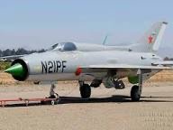
-One of the posts above mentioned disturbance losses due to the blunt shape of the nose of the cone filter. Can I avoid this disturbance loss into my E-0995 cone filter by attaching a long tapered extension to the round blunt nose of the filter? À la MIG-21 intake?
2 questions:
- we have fuel injection yet I see the term “carb loss” often in this thread. Is “carb” in this context short for “induction?”
-One of the posts above mentioned disturbance losses due to the blunt shape of the nose of the cone filter. Can I avoid this disturbance loss into my E-0995 cone filter by attaching a long tapered extension to the round blunt nose of the filter? À la MIG-21 intake?
Attachments
- we have fuel injection yet I see the term “carb loss” often in this thread. Is “carb” in this context short for “induction?”
Yes.
-One of the posts above mentioned disturbance losses due to the blunt shape of the nose of the cone filter. Can I avoid this disturbance loss into my E-0995 cone filter by attaching a long tapered extension to the round blunt nose of the filter? À la MIG-21 intake?
Steve wasn't objecting to the bluntness. The concern is reduction of the annular space available between the filter nose and the enclosure.
I too have been very satisfied with AI results only to find real world testing as I have posted in this thread shows otherwise.Found my filter no.:
K&N E-0995. It fits a stock 4.0L Ford Explorer.
A.I. math says the following:
-the Explorer redlines at 6000 rpm. At 85% VE that’s 360 CFM of air.
-at the same VE, the 540 Lyc at 2700 rpm pumps 357 CFM of air.
I therefore proclaim my K&N cone unit to be as satisfactory in my plane as it is in the truck it was designed for.
No doubt there are gains to be had with a larger filter, but I’m so glad I will now loose no sleep over that fact! ;-)
The k&N E-0995 is too small for the IO-540
andoman
Well Known Member
I knew my search would yield feel good results at best. My “satisfied“ post was ment tongue in cheek.
As I followed this thread I was hoping the experience of the experts in the group would come through and I was not disappointed!!! Thanks again.
My engine runs clean and my performance nos. seem close to other rockets with 260HP 540’s. I do have an RSA-5 Bendix servo which I understand is marginal. Perhaps my marginal servo and marginal air filter get along…
Last edited:
Thanks for the much more comprehensive report. Lots of good stuff here, and lots of good comments following.Hey Steve,
Sorry for the sketchy summary , Don at Airflow Performance is extremely though and tested the air intakes every which way, with, without filter , Alt Air Door etc.
The filter supplied from James Aircraft Parts for the MK IV Filter assembly was a K&N -E0995
KN Air Filter E-0995
A few things to add:
The pressure drop for your installation with the filter installed is about 4.5" H2O more than filter removed at 1800 PPH. That is about 1/3 in. Hg. While that would be significant for an always-filtered intake, I would consider that acceptable for a ram-air intake that you select filtered air only for ground ops. (low power settings except for take-off -- and if take-off performance is critical, you could go unfiltered.)
I'm having a hard time comparing filter medium area on the E-0995 with the filters we use in our ram-air intakes, because the physical dimensions include a wide rubber flange at the base, and the domed nose at the front. If you could post the base diameter, nose diameter, and length of just the filter element, I can compare and comment on that relative to our filter sizes. Although DanH correctly points out that it is the wetted area (including the pleats) that really matters, for comparison purposes I just use the equivalent smooth cone area. And its true that that is not a fair comparison to flat filters that have much deeper pleats. But for comparing various different conical filters, it is a useful metric.
And DanH correctly noted that my concern about the filter housing is the rather small annular flow path to get around the nose of the filter. It is also somewhat less than ideal that the rubber dome nose transition to the filter has a sharp corner. But short of putting a bigger dome over it, there isn't much we can do about that. One would not want a conical 'spike' on the front as Andoman suggested -- those are for supersonic flow. For subsonic flow, a round dome is the right approach, but best if it becomes tangent to the slope of the filter element at the front. With the narrow annular passage, and the corner at the edge of the dome, I suspect that a fair fraction of that 1/3 in. Hg. loss is not from the filter itself, but rather the overly restrictive flow path getting air to the filter.
Our Type-3 filtered ram-air intake has as big an annular bypass channel as I could make and reasonably expect people to fit the canister into their cowl. It has a flow area equal to a 2.8" round duct. So you can see, with a 80mm SDS throttle body, or an FM-300 throttle body, even our design would be somewhat restrictive. DanH's data suggests that the additional loss from that restriction is something less than 1.0 in. H2O (comparing his FM-200 and FM-300 performance at similar airflow). The FM-300 is SO big, able to pass SO MUCH air, I really wonder if it needs to be that big -- if you fly with one, how far back do you have to pull the throttle before you actually notice a power reduction? I bet you get the throttle back 1/3 or more before you even begin to be able to tell.
Having spent quite a bit of time trying to come up with a good alternate air valve, I can tell you, it is really tough to get enough flow area. Not just the valve itself, but the whole flow path to get air in where the filter is. It is easy to see how the expedience of trying to fit a flap on the back somewhere would just not be even close to big enough. We can rationalize that on the extremely rare event that you swallow just the right size bird, or plastic bag, or really severe snowfall, you would be content to have partial power to get safely to where you are going, even if the performance has been degraded. But, with all that, I have finally come up with a design that I think will work well, and has a flow area just about equal to our ram-air butterfly valve. It is a spring-loaded suck-in valve, so no control cable needed, and will respond instantly to an obstructed inlet with no pilot action. The challenge will be getting it to seal well when closed so that it doesn't spill ram air into the lower cowl area -- which has two bad effects - one - it wastes intake pressure, and two - it raises the lower cowl plenum pressure some, reducing engine cooling flow. So I want it to seal best I can. I will be prototyping that valve this winter, so stay tuned.
For subsonic flow, a round dome is the right approach, but best if it becomes tangent to the slope of the filter element at the front.
Something like this. Here the cap is a little beyond tangent. BTW, this is a experiment to modify a big cylindrical filter into a large cone by removing the original flat end plate and squeezing the media into a new cap. The cap is fiberglass. Adhesive is room temp cure urethane.

Having spent quite a bit of time trying to come up with a good alternate air valve, I can tell you, it is really tough to get enough flow area. Not just the valve itself, but the whole flow path to get air in where the filter is. It is easy to see how the expedience of trying to fit a flap on the back somewhere would just not be even close to big enough. We can rationalize that on the extremely rare event that you swallow just the right size bird, or plastic bag, or really severe snowfall, you would be content to have partial power to get safely to where you are going, even if the performance has been degraded.
I think we're all ok with some small loss of performance when operating on alternate air. It's an emergency supply. However, an effective alternate supplies air to the space behind the filter. Nothing else passes a FOD blockage test, including the Bower and all its derivatives.
The James inlet tested above is a true alternate air, but it is grossly undersized even for a 390 (loss is 46" H2O 1400 pph...holy crap!).
It should be possible to move the air door off the cone so it could be enlarged. Plenty of space on either side. I'd probably go to the left, because the closest pipe on the left would be the #2 intake...cooler air.

The guillotine door provided on the side of a Vans's snorkel is probably better in terms of loss, but (1) I'll bet a lot of them stick with the engine turning and the filter blocked, and (2) it's pilot operated, rather than automatic. It is possible to do a good suck-in door.
Which brings up another issue, designing to reduce the possibility of ingesting loose hardware. Steve mentioned sealing; even seal material is a risk if it comes loose and ends up in the throttle body. So, consider forming the door in place to eliminate the need for a seal. All it takes is some wax and PVA on the case.
I've never like piano hinge on an intake. Eliminate all fasteners and hinge parts using an axle through the side of the enclosure. This one used piano wire encapsulated into the door layup. Because the door was formed in place and thus fits precisely in the opening, it does not move due to vibration, so hinge wear is near zero.


Last edited:
Part of the challenge is not just the intake area of the door itself, but any and all flow restrictions downstream. The big door that Dan sketched in white is great, but the flow still has to go through that little slot. With the conical filter, its pretty hard to get any significant intake area behind the filter because that just adds to the length, which is already an integration issue in the cowl.Something like this. Here the cap is a little beyond tangent. BTW, this is a experiment to modify a big cylindrical filter into a large cone by removing the original flat end plate and squeezing the media into a new cap. The cap is fiberglass. Adhesive is room temp cure urethane.
View attachment 105116
I think we're all ok with some small loss of performance when operating on alternate air. It's an emergency supply. However, an effective alternate supplies air to the space behind the filter. Nothing else passes a FOD blockage test, including the Bower and all its derivatives.
The James inlet tested above is a true alternate air, but it is grossly undersized even for a 390 (loss is 46" H2O 1400 pph...holy crap!).
It should be possible to move the air door off the cone so it could be enlarged. Plenty of space on either side. I'd probably go to the left, because the closest pipe on the left would be the #2 intake...cooler air.
View attachment 105121
The guillotine door provided on the side of a Vans's snorkel is probably better in terms of loss, but (1) I'll bet a lot of them stick with the engine turning and the filter blocked, and (2) it's pilot operated, rather than automatic. It is possible to do a good suck-in door.
Which brings up another issue, designing to reduce the possibility of ingesting loose hardware. Steve mentioned sealing; even seal material is a risk if it comes loose and ends up in the throttle body. So, consider forming the door in place to eliminate the need for a seal. All it takes is some wax and PVA on the case.
I've never like piano hinge on an intake. Eliminate all fasteners and hinge parts using an axle through the side of the enclosure. This one used piano wire encapsulated into the door layup. Because the door was formed in place and thus fits precisely in the opening, it does not move due to vibration, so hinge wear is near zero.
The road I’m currently following (RV-10, modified James Cowl for horizontal injection, FM-200 on a Cold Air Sump IO-540).
I think Dusty has the right approach to address the limite space between the FM-200 and the cowl engine air inlet. I’ll know the hard dimensions next month when I finally mount the engine. Dusty’s filter photo attached.
This might evolve to something mimicking a mockup done by Jimmy at James Cowl a couple of years ago. The filter would be horizontal, the airflow changing direction to vertical through the filter and then back horizontal to the FM-200.
For alternate air I’m hoping to be able to fit the standard AirFlow Performance duct:

Carl
I think Dusty has the right approach to address the limite space between the FM-200 and the cowl engine air inlet. I’ll know the hard dimensions next month when I finally mount the engine. Dusty’s filter photo attached.
This might evolve to something mimicking a mockup done by Jimmy at James Cowl a couple of years ago. The filter would be horizontal, the airflow changing direction to vertical through the filter and then back horizontal to the FM-200.
For alternate air I’m hoping to be able to fit the standard AirFlow Performance duct:
FM-200 Alternate Air Duct - AIRFLOW PERFORMANCE
airflowperformance.com
Carl
Attachments
Stumbled into something. There is a whole bunch of interesting filter elements here:
https://www.sprintfilter.net/automotive/kit/
They're only posting one picture for all the universal cones, so you must look at the specifications for each and use some imagination.
https://www.sprintfilter.net/automotive/filtercategory/category/conicals/5
There's a lot more on other pages. They seem to have several at least four different filter fabrics, with different micron ratings, and waterproof, whatever that means.
Download brochure.
Last edited:
Part of the challenge is not just the intake area of the door itself, but any and all flow restrictions downstream. The big door that Dan sketched in white is great, but the flow still has to go through that little slot. With the conical filter, its pretty hard to get any significant intake area behind the filter because that just adds to the length, which is already an integration issue in the cowl.
Well, let's imagineer something suitable for the 4-cylinder stuff, for those desiring to stay with a cone filter.
Generally speaking there is plenty of free space to the left and right of the throttle body entry. So, consider a rectangular box sandwiched between the cone and the TB. It might be something like 10"W x 6"H x 1" D...no thicker than the existing alt air section on the James inlet. Two spring loaded doors, one each side, say 5"H x 2"W. The smallest flow area would be about 6"H x 1" W. Got two of those, so 12 sq in, which is roughly equal to a 4" throat on a TB...plenty of area for a practical alternate air.
Practical fabrication: Make the box in two parts, front and back, for easy layup and mold release. Pull the front from the mold, cut the door openings, wax it and spray with PVA, drop it back in the mold, and do the door layups in place so no seal is required. Pop them out, trim, drop them back in, and encapsulate the wire hinges. The springs are external.

Last edited:
I was thinking about something like that. But my current cone filter, just like the Bower, uses the rubber flange of the filter to attach to the throttle body.Well, let's imagineer something suitable for the 4-cylinder stuff, for those desiring to stay with a cone filter.
Generally speaking there is plenty of free space to the left and right of the throttle body entry. So, consider a rectangular box sandwiched between the cone and the TB. It might be something like 10"W x 6"H x 1" D...no thicker than the existing alt air section on the James inlet. Two spring loaded doors, one each side, say 5"H x 2"W. The smallest flow area would be about 6"H x 1" W. Got two of those, so 12 sq in, which is roughly equal to a 4" throat on a TB...plenty of area for a practical alternate air.
Practical fabrication: Make the box in two parts, front and back, for easy layup and mold release. Pull the front from the mold, cut the door openings, wax it and spray with PVA, drop it back in the mold, and do the door layups in place so no seal is required. Pop them out, trim, drop them back in, and encapsulate the wire hinges. The springs are external.
View attachment 105193
One could put a snout on your box for the flange, but that would result in a total forward shift of 1.63" of the filter canister. Assuming we still want the diffuser and bypass channel on the front of the canister (for either my Type-2 or Type-3), that length addition is not possible with the stock Van's cowl. Could perhaps fit in the additional length of a James or Showplanes cowl?
The other option would be to get a cone filter with no flange, and make an attachment for the rear rim of the filter onto the alt air box, similar to the little clips you made for Peter or just bond the filter rear ring into the box (which would make replacement 'complicated'), but this could be done with only a 3/8" forward shift of the filter canister.
Some minor fitment challenges such as the interference with the starter motor and alternator, but some clever shaping of the air box could deal with that. Might not be able to maintain the full 6" height
Where this idea would make the most sense is an always-filtered ram-air intake, now with a true alternate air source. For those that want unfiltered ram-air with a filtered alternate air source for ground ops, I still think my Type-1 is the best option. If I put the round suck-in door I am prototyping at the cooling ramp, that will alleviate the small reverse-flow issue during ram-air ops. True that this isn't a fully alternate air source, since it comes in upstream of the filter, but the possible scenario of a plugged ram-air intake AND some kind of fouling in the cooling ram inlet just seems so unlikely that it falls off the bottom of the risk-management chart in my mind.
Where this idea would make the most sense is an always-filtered ram-air intake, now with a true alternate air source.
Correct. As noted previously, the filter loss for an E-0990 cone in a James can at 1300 pph is only 3.9" H2O, and would be under 2" H2O in cruise at altitude. I doubt there will be more than 1" H2O between a well done canister with the E-0990 and the open butterfly in an unfiltered condition. It's not enough for the 540, but it's fine for a 4 cyl.
For those that want unfiltered ram-air with a filtered alternate air source for ground ops, I still think my Type-1 is the best option.
I agree, but the data says the filtered ram would cost something less than 0.1 Hg in cruise. Put a Type 1 on a flow bench and see how that compares with butterfly hardware in a throat.
Last edited:
Supersonics guy can weigh in here. The inlet on the MiG is addressing a different problem. For an aircraft designed for supersonic speeds, the inlet needs to set up a system of shock waves to slow the flow to subsonic so it can feed the engine. I believe the MiG uses a two shock design. The first shock is oblique (at an angle roughly equal to the angle between the tip of cone and the inlet lip). The second is a normal shock, between the lip and the max diameter of the cone. This second shock slows the flow to less than Mach 1. By using 2 shocks, the the pressure loss is reduced. For low subsonic speeds, a pitot inlet is most efficient. The caveat is, as mentioned in Steve Smith's post above. The minimum gap between the initial diameter of the filter and the housing must be a larger area than the inlet to the servo. Otherwise the inlet is the throttle.I have found this thread to be MOST enlightening and relevant. . Thanks to all.
2 questions:
- we have fuel injection yet I see the term “carb loss” often in this thread. Is “carb” in this context short for “induction?”
-One of the posts above mentioned disturbance losses due to the blunt shape of the nose of the cone filter. Can I avoid this disturbance loss into my E-0995 cone filter by attaching a long tapered extension to the round blunt nose of the filter? À la MIG-21 intake?
So if my FM300R servo that is 4" dia do I need a 4" dia inlet in my cowl. I was always under the impression that the ram air effect made up the difference and even the 3" inlet if my math was some what right was good down to 100kts and anything under 100kts it would suffer losses.Supersonics guy can weigh in here. The inlet on the MiG is addressing a different problem. For an aircraft designed for supersonic speeds, the inlet needs to set up a system of shock waves to slow the flow to subsonic so it can feed the engine. I believe the MiG uses a two shock design. The first shock is oblique (at an angle roughly equal to the angle between the tip of cone and the inlet lip). The second is a normal shock, between the lip and the max diameter of the cone. This second shock slows the flow to less than Mach 1. By using 2 shocks, the the pressure loss is reduced. For low subsonic speeds, a pitot inlet is most efficient. The caveat is, as mentioned in Steve Smith's post above. The minimum gap between the initial diameter of the filter and the housing must be a larger area than the inlet to the servo. Otherwise the inlet is the throttle.
So if my FM300R servo that is 4" dia do I need a 4" dia inlet in my cowl. I was always under the impression that the ram air effect made up the difference ....
Dynamic pressure is available with either inlet diameter.
Some assumptions are required, so I'll use 200 ktas, a 540 @2700 with typical VE around 0.875, and treat the inlet as a ring and tube. Including the effect of dynamic pressure, a 4"D inlet would produce roughly 0.4"Hg more than a 3"D inlet at 1000 ft, and 0.3 more at 8000 ft.
Recall dynamic pressure is 1/2 density * velocity squared. In a closed end pitot system we add it to static pressure by halting its motion. Here the system is not a closed end pitot, so conceptually the available dynamic pressure at the servo would be based on the difference between freestream velocity and velocity through the ring.
Ya'll check me:

Carl,The road I’m currently following (RV-10, modified James Cowl for horizontal injection, FM-200 on a Cold Air Sump IO-540).
I think Dusty has the right approach to address the limite space between the FM-200 and the cowl engine air inlet. I’ll know the hard dimensions next month when I finally mount the engine. Dusty’s filter photo attached.
This might evolve to something mimicking a mockup done by Jimmy at James Cowl a couple of years ago. The filter would be horizontal, the airflow changing direction to vertical through the filter and then back horizontal to the FM-200.
For alternate air I’m hoping to be able to fit the standard AirFlow Performance duct:
FM-200 Alternate Air Duct - AIRFLOW PERFORMANCE
airflowperformance.com
Carl
We explored this at length and made a flying prototype but ended up with a very creative flat plate filter without the scoop. We have achieved the pressure recovery as per Dan H latest post and as Dan commented, the Alt Air is by far a major challenge.
Sorry I am a bit vague with our details, however this is a major group effort and will share more when I can.
Carl, re the Airflow Performance duct for the Alt Air, there is just no room. With the SDS 90mm being half the length of the FM300B , there is still no room.
The Alt Air has to be part of the filtered airbox assy.
We expect the first production units will be finished in February '26, so not long to wait.
This is where we started ....., This version was a good proof of concept of what can be fitted in a cowl but the scoop required added too much drag.
it all started carving foam and ended up with high res digital scans and CFD testing. Many test articles are now in the dust bin.
Version 0


A many of you know, I am one of the directors of our Australian Youth program , Flight Youth Engineering , this project and its success can trace its roots to mentoring high school students and igniting the passion within our young people. Some of these students are now 4th year engineering students and their skill set in the digital age is what this program success will be based on.
I am very much enjoying being the apprentice again in this digital age. so many school programs aim very low and get very low results. We aim to the highest standard and are achieving very high results with motivated students.
One of our completed aircraft,
Flight Youth Engineering
FYE Corrosion Protection
There are so many talented members on these forums, can I please encourage you to spend some time with young students be for the morality of man catches up with you.
