Thought I'd re-open this thread as it now anppears to affect me. I had posted my "off-camber" nose gear problem in a
different thread and I'm posting here rather continuing the hijack of
that thread.
The issue was my front wheel and axle being off camber...the axle wasn't parallel to the earth and this made engagement of my Best Tug arms on the axle bolt problematic. Many of the posted theories suggested a bent nose gear leg but in discussing it with both
@AlexPeterson and
@petehowell I was more inclined to focus on the nose gear leg and its securing bolt, one of the foci in this discussion in this thread, which Alex pointed me to. Alex flew up today to help me out a bit with the diagnostic process. Not being a builder, his input provided me with the defining light-bulb moment.
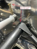
First move was pushing forward on the left wing, applying a little ground yaw. This re-aligned the axle to earth-parallel and the tug engaged the axle for the first time as Mark Patey designed it. Then we unweighted the nose gear did a wiggle test, and sure enough, the nose gear was not secure in the engine mount socket. The gear leg didn't wiggle front/back or side/side...it
rotated a bit in the socket along its long axis. This is what was allowing the nose-wheel to sit off-camber and preventing the tug from hitting the axle symmetrically on both ends. Watching the motion clearly while observing the socket/bolt, we could see that the hole in the gear leg is just a bit too big thus creating a bit of rotational slop and that rotation of the gear leg caused the camber of the nosewheel to change. Nose gear leg and engine mount socket appear to be fine. No sign of any wiggle or cracks in the
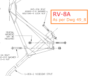
I'm going to address this, with Alex's guidance, by getting some close-tolerance bolts as described in this thread and seeing if I can re-establish the proper rotational orientation of the nose gear portion of the engine mount.
View attachment 98074


 )
)

")


 Thanks for sharing!
