
Van's Air Force
You are using an out of date browser. It may not display this or other websites correctly.
You should upgrade or use an alternative browser.
You should upgrade or use an alternative browser.
Starter ground
- Thread starter wirejock
- Start date


I know some builders run a dedicated ground to the starter.
Is the case grounded?
Which bolt did you use?
Is this one avaiable?
View attachment 10962
Not necessary provided the engine block/case is grounded with an equivalent size wire to the firewall ground point.
Do you have the OP drawings that show this connection?
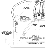
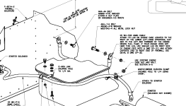
The lug that you've circled is the mounting point for the alternator torque strap.
Last edited:
Carl Froehlich
Well Known Member
I ground the engine on the starter ground lug on all three RVs, using the same #2 or #4 welding wire that provides power to the starter.
The starter is what takes the current, why not provide it with the best ground? The amount of metal to metal contact between the starter and the engine case is huge so no issue with the engine itself being grounded. And as pointed out for our RVs there is typically a strap between the alternator and the starter - so a byproduct is a solid ground for the alternator.
I note with interest the continued use of fraying ground straps under greasy engine bolts. There are better options.
Carl
wirejock
Well Known Member
Ground
Thanks Carl. That's what I would like to install. #2 battery to starter.
Which is ground? One is labeled for power so that one is obvious.
Where on the starter did you tie the ground?
I also plan a ground to the engine case.

I ground the engine on the starter ground lug on all three RVs, using the same #2 or #4 welding wire that provides power to the starter.
The starter is what takes the current, why not provide it with the best ground? The amount of metal to metal contact between the starter and the engine case is huge so no issue with the engine itself being grounded. And as pointed out for our RVs there is typically a strap between the alternator and the starter - so a byproduct is a solid ground for the alternator.
I note with interest the continued use of fraying ground straps under greasy engine bolts. There are better options.
Carl
Thanks Carl. That's what I would like to install. #2 battery to starter.
Which is ground? One is labeled for power so that one is obvious.
Where on the starter did you tie the ground?
I also plan a ground to the engine case.
Thanks Carl. That's what I would like to install. #2 battery to starter.
Which is ground? One is labeled for power so that one is obvious.
Where on the starter did you tie the ground?
I also plan a ground to the engine case.
View attachment 10964
The starter case is the ground...and that is a picture of the starter solenoid, not the starter motor.
Last edited:
I ground the engine on the starter ground lug on all three RVs, using the same #2 or #4 welding wire that provides power to the starter.
The starter is what takes the current, why not provide it with the best ground? The amount of metal to metal contact between the starter and the engine case is huge so no issue with the engine itself being grounded. And as pointed out for our RVs there is typically a strap between the alternator and the starter - so a byproduct is a solid ground for the alternator.
I note with interest the continued use of fraying ground straps under greasy engine bolts. There are better options.
Carl
Why add the weight? The engine case is more than capable of carrying the return ~300A to a ground point.
Indeed - this is working fine for me. The part of the engine that the starter bolts to is very clean, flat, un-anodized metal, securely bolted, so is probably conducting pretty good to the engine case.Why add the weight? The engine case is more than capable of carrying the return ~300A to a ground point.
I put my dual grounds on the bolts holding part of the baffle to the engine case, and it's working great. Never a hint of slowdown while cranking.

http://www.rv8.ch/ground-point-on-firewall/
RV-7
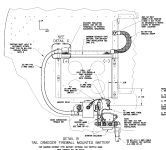
Attached pictures/examples for RV-7, with IO-360-A1B6 (or IO-390-A,C...) the location of the case lug ***MAY*** be different since no two lycoming cases are the same")
Drawing excerpt from OP-30 with Odyssey PC-680 Firewall *and* additional firewall ground point from the same drawing for the Concorde battery.
<edit> Real life picture is rotated CCW 90° *sigh*
As Carl mentioned, use the correct wire size and terminations...
<edit> ...and use MEK or Acetone to remove any paint at the lug.
Attached pictures/examples for RV-7, with IO-360-A1B6 (or IO-390-A,C...) the location of the case lug ***MAY*** be different since no two lycoming cases are the same
Drawing excerpt from OP-30 with Odyssey PC-680 Firewall *and* additional firewall ground point from the same drawing for the Concorde battery.
<edit> Real life picture is rotated CCW 90° *sigh*
As Carl mentioned, use the correct wire size and terminations...
<edit> ...and use MEK or Acetone to remove any paint at the lug.
Attachments
Last edited:
BillL
Well Known Member
Why add the weight? The engine case is more than capable of carrying the return ~300A to a ground point.
I would agree, there is a Lycoming designated lug on the right lower aft side of the case that I used on an M1B. The starter is already well grounded to the case.
Flat ground cable expanded with a second inside is more than adequate for amps and convenient to the battery post per Vans design.
Last edited:
wirejock
Well Known Member
Starte
Yes. I know. Carl mentioned a ground lug. I've swapped a lot of starters on autos and it got me wondering if somehow airplane starter was different.
Still waiting for.an answer to my question on where he grounded the starter.
The starter case is the ground...and that is a picture of the starter solenoid, not the starter motor.
Yes. I know. Carl mentioned a ground lug. I've swapped a lot of starters on autos and it got me wondering if somehow airplane starter was different.
Still waiting for.an answer to my question on where he grounded the starter.
Yes. I know. Carl mentioned a ground lug. I've swapped a lot of starters on autos and it got me wondering if somehow airplane starter was different.
Still waiting for.an answer to my question on where he grounded the starter.
Starters don't have a provision for connecting a ground cable, as the industry standard (auto AND aircraft) is to ground on the engine block and the starter's contact with the block is the ground path. 10's of millions of cars setup this way with good track records.
Not knocking anyone doing it, but is unnecessary if the engine block is properly grounded. Just look at the contact area between the tiny odyssey tab and the #2 lug and you'll see how little surface area is required to pass 300 amps. Better still look at your solenoid connection. Contact area is just a 5/16 jam nut. It is wise to use #2 to the block, but most do it using a #2 ground strap (very thin strands in a braid, designed for constant flexing) from the frame to the block. Not wise to use a #2 cable to the block unless it is a welding cable with very fine strands. A welding cable will not be as robust as a ground strap, otherwise, auto companies would have used it instead of inventing ground straps; welding cable is cheaper to make and auto companies like cheap UNLESS it doesn't hold up.
Larry
Last edited:
The only places you could attach a large lug from a heavy ground cable are structural fasteners for either attaching the starter to the engine or the or the brace link from the alternator.
Installing a soft (copper) lug on any of these bolts is not a good idea which is why a using a hole on the back of the engine case with the surface properly cleaned of paint, etc., is the best, not to mention lightest option.
If you really wanted to do this I guess you could use an extra long bolt for the alternator brace bare lug (circled in your first photo) and then attach the cable with a nut on the aft side but I think this would be a much more inferior ground than using the engine case but with zero benefit in my opinion.
Last edited:
Also worth mentioning. I'm not worried about my case ground coming off or getting oily/ corroded with it's current location (base of oil fill neck using the provided hole by Lycoming). I inspect it every preflight by looking in the oil door. It is very accessible to see. If it is covered in oil/grime/grease you will see it. Also, the likely hood of the starter ground becoming covered in oil doesn't disappear if connected at the starter.
Just some thoughts on the matter. Also put me in the camp of unnecessary weight. In all reality it will work just fine either way. I'm just glad you are getting the project cranked out so we can fly together Larry!
Just some thoughts on the matter. Also put me in the camp of unnecessary weight.
In all reality it will work just fine either way. I'm just glad you are getting the project cranked out so we can fly together Larry!smithflys23
Well Known Member
Engine ground
My starter is grounded to the engine case.
While on the topic of engine grounding....
Here’s what mine looks like. The airframe ground is attached to the engine mount. Is this acceptable?

My starter is grounded to the engine case.
While on the topic of engine grounding....
Here’s what mine looks like. The airframe ground is attached to the engine mount. Is this acceptable?
My starter is grounded to the engine case.
While on the topic of engine grounding....
Here’s what mine looks like. The airframe ground is attached to the engine mount. Is this acceptable?
View attachment 10981
I would not recommend attaching the ground like that. The bolts, nuts and washers all have standards to which they made, including compression strength. Unless you have a report that says the copper end lug on that cable is just as strong in compression as the steel washer and bolt, I would avoid using it as a structural fastener. I think over time, the copper will crush and you'll lose preload on that bolt.
I would not recommend attaching the ground like that. The bolts, nuts and washers all have standards to which they made, including compression strength. Unless you have a report that says the copper end lug on that cable is just as strong in compression as the steel washer and bolt, I would avoid using it as a structural fastener. I think over time, the copper will crush and you'll lose preload on that bolt.
This is correct.
Copper cable lugs on a structural bolt is not a good idea.
A connection to engine assemblie hardware is not ideal either.
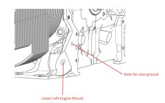
Most all Lyc engine cases have a hole in the case web that is directly aft of the base of the dip stick tube. This hole is used for no purpose on an RV so it makes it a great ground cable attach point (just be sure to fully remove an paint / primer down to bare metal for a good electrical bond).
Last edited:
wirejock
Well Known Member
Buss bar
Thanks everyone for the info. The pictured and drawings help a lot. I will switch to a case ground.
As long we are, sort of, on the subject.
The plans call for two copper bars between the contactors.
The stuff I got from AS is .138" thick. It barely fits the output of the Master. No way two will fit.
What did you use?
Next question
The contactors studs are not steel.
What is the torque spec for the contactor nuts?
smithflys23
Well Known Member
I would not recommend attaching the ground like that. The bolts, nuts and washers all have standards to which they made, including compression strength. Unless you have a report that says the copper end lug on that cable is just as strong in compression as the steel washer and bolt, I would avoid using it as a structural fastener. I think over time, the copper will crush and you'll lose preload on that bolt.
Thanks for the feedback. I’ll look at remediating this.
Thanks everyone for the info. The pictured and drawings help a lot. I will switch to a case ground.
As long we are, sort of, on the subject.
The plans call for two copper bars between the contactors.
The stuff I got from AS is .138" thick. It barely fits the output of the Master. No way two will fit.
What did you use?
Next question
The contactors studs are not steel.
What is the torque spec for the contactor nuts?
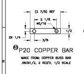
P20 buss bar detail from the OP-12 DWG, see attached. Made from .063"
I went by "feel & sight" for the torque -- use two wrenches, one to hold the stud and keep from turning, tighten the nut down while observing the lock washer, tighten nut until lock washer is flat.
I'll look around for the mfg. recommended values (White/Rogers was the mfg. IIRC)
*edit - W/R Data sheet suggests 44 to 55 in.lb. for Contact Terminal Stud nut torque.*
B
Attachments
Last edited:
Thanks for the feedback. I’ll look at remediating this.
Traditional ground straps often have steel terminals instead of copper to allow this type of connection.
Traditional ground straps often have steel terminals instead of copper to allow this type of connection.
Hmmm -- I believe the terminals on WH-P25 are tin flashing over annealed copper (ASTM B-512).
wirejock
Well Known Member
Buss bar
Thanks
I suppose the question still stands.
Will one bar .138" suffice or is there some electronic reason for two .063" bars?
If Vans wanted a certain bar, I wish they would have included it in my FWF kit!
P20 buss bar detail from the OP-12 DWG, see attached. Made from .063"
I went by "feel & sight" for the torque -- use two wrenches, one to hold the stud and keep from turning, tighten the nut down while observing the lock washer, tighten nut until lock washer is flat.
I'll look around for the mfg. recommended values (White/Rogers was the mfg. IIRC)
*edit - W/R Data sheet suggests 44 to 55 in.lb. for Contact Terminal Stud nut torque.*
B
Thanks
I suppose the question still stands.
Will one bar .138" suffice or is there some electronic reason for two .063" bars?
If Vans wanted a certain bar, I wish they would have included it in my FWF kit!
Thanks
I suppose the question still stands.
Will one bar .138" suffice or is there some electronic reason for two .063" bars?
If Vans wanted a certain bar, I wish they would have included it in my FWF kit!
Some of us used copper pipe from Home Depot, flattened it, and fashioned our own bars...
All other things being equal -- you should be fine with a .138" bar...
*edit -- the math ---*
The reason? They (Van's) are trying to create an equivalent conductor as 2ga wire; 2ga wire has a diameter of ~.258", thus a cross sectioned area of ~.052in.sq. A single piece of copper 1/2" wide and .063" thick has a cross section of .0315in.sq., doubling that yields .063in.sq --- just a hair more than 2ga wire.
Wall thickness for 1" copper tubing is between .035" and .065"
Last edited:
Thanks
I suppose the question still stands.
Will one bar .138" suffice or is there some electronic reason for two .063" bars?
If Vans wanted a certain bar, I wish they would have included it in my FWF kit!
Works just dandy for me! They are just trying to get a certain amount of cross section as already mentioned.
Hey Larry, I'm working on the wiring now if you want to check mine. On the master and the starter Relay/solenoids you need the OP-30 for the Tri gear which shows a ES WH-P4F 2 AWG cable to connect both master and starter relays instead of the copper bars.
Bob,
Look at OP-30, Detail B and DWG 31A Note 2.
IMHO, you shouldn't bother with the Concorde, especially on -A model, as it adds even more weight to firewall...
YMMV.
B
Hey Brian, looked at OP-31 note 2 was :
2. Both Tail Dragger and Tricycle gear battery battery configurations shown.
So If I am missing something which is common, To me that just shows the wiring from engine Battery to panel switches that will be deferent from where the battery is mounted.
Larry has an RV7A so I just assumed his Battery, Master and Stater Relay/ Solenoid should be in the Tricycle A Detail instead of the Detail B for RV7 tail dragger which I have. Cheers Bob
Hey Brian, looked at OP-31 note 2 was :
2. Both Tail Dragger and Tricycle gear battery battery configurations shown.
So If I am missing something which is common, To me that just shows the wiring from engine Battery to panel switches that will be deferent from where the battery is mounted.
Larry has an RV7A so I just assumed his Battery, Master and Stater Relay/ Solenoid should be in the Tricycle A Detail instead of the Detail B for RV7 tail dragger which I have. Cheers Bob
DWG 31A Note 2. The PC680 is Optional for the 7A/9A..
He's using the Odyssey PC680 configuration, because he has a large oil cooler mounted on the firewall on the left side.
Attachments

Last edited:
Some of us used copper pipe from Home Depot, flattened it, and fashioned our own bars...
All other things being equal -- you should be fine with a .138" bar...
*edit -- the math ---*
The reason? They (Van's) are trying to create an equivalent conductor as 2ga wire; 2ga wire has a diameter of ~.258", thus a cross sectioned area of ~.052in.sq. A single piece of copper 1/2" wide and .063" thick has a cross section of .0315in.sq., doubling that yields .063in.sq --- just a hair more than 2ga wire.
Wall thickness for 1" copper tubing is between .035" and .065"
This is all true, but for completeness, this equivalency only works for DC systems. If you're pushing AC through the conductor, a stranded 2 gauge cable will conduct better than solid copper with the same cross section area.
https://en.wikipedia.org/wiki/Skin_effect
smithflys23
Well Known Member
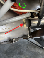
Most all Lyc engine cases have a hole in the case web that is directly aft of the base of the dip stick tube. This hole is used for no purpose on an RV so it makes it a great ground cable attach point (just be sure to fully remove an paint / primer down to bare metal for a good electrical bond).
Is this the spot you were referring too?
I'm not sure why the pics attached sideways.


Is this the spot you were referring too?
I'm not sure why the pics attached sideways.
View attachment 11403
View attachment 11404
Yup, that's one of them...
Is this the spot you were referring too?
I'm not sure why the pics attached sideways.
View attachment 11403
View attachment 11404
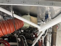
That's what I used.
smithflys23
Well Known Member
Yup, that's one of them...
Ok, now that We’ve established A good place to ground the engine case, what about the firewall ground? I don’t have a dedicated ground bar on the firewall. Mine is grounded on the engine mount, which was decided to be less than ideal.
What about using the rudder pedal anchor point?

Ok, now that We’ve established A good place to ground the engine case, what about the firewall ground? I don’t have a dedicated ground bar on the firewall. Mine is grounded on the engine mount, which was decided to be less than ideal.
What about using the rudder pedal anchor point?
View attachment 11415
Yes, provided that 100% of the 2GA wire lug is in contact with the firewall, or that metal strap...
See green circle...Can you drill out this rivet and put an AN4 or AN5 bolt in there?
Attachments
Last edited:
Carl Froehlich
Well Known Member
I would not consider this as viable. Ground the engine to the same place you have the battery(s) grounded on the firewall. If the battery(s) are not grounded on the firewall, then I assume you have a rear mounted battery and are using a nearby airframe ground. Is this correct? If so, then I recommend a simple bolt on the firewall, that captures both the SS firewall as well as a supporting firewall angle. On the cabin side run a cable from this same bolt to whatever you are using for your common panel ground.
Side note - for my RV-10 and RV-8 rear mounted batteries I did belt and suspenders - a local ground and a ground wire to the common firewall ground.
Carl
smithflys23
Well Known Member
See green circle...Can you drill out this rivet and put an AN4 or AN5 bolt in there?
It’s a flying airplane, so it would be a pain, but possible.
smithflys23
Well Known Member
If the battery(s) are not grounded on the firewall, then I assume you have a rear mounted battery and are using a nearby airframe ground. Is this correct?
Correct.
Actually, I have to fix the rear battery ground as well. One of the “Pros” ground the battery on the frame of the battery box, instead of on the airframe itself.
Thanks, Carl.
It’s a flying airplane, so it would be a pain, but possible.
See Carl's comment -- (not about belt/suspenders); where's the (-) terminal on your battery connected?
smithflys23
Well Known Member
See Carl's comment -- (not about belt/suspenders); where's the (-) terminal on your battery connected?
It’s a rear mounted battery, and the battery negative is attached to the frame of the battery tray. I don’t have a picture. I intend to correct this, and ground it on one of the airframe angles. I finally got the correct hardware together.
That might already be ok if the battery tray is well-grounded to the airframe. When I had my tray in the back it had several square inches of contact with the airframe, with I believe 3 10-32 countersunk screws holding it down.It’s a rear mounted battery, and the battery negative is attached to the frame of the battery tray. I don’t have a picture. I intend to correct this, and ground it on one of the airframe angles. I finally got the correct hardware together.

