

I have an externally regulated alternator with crow bar OV protection. Despite their high reliability, they can fail.
I also have an electronically dependent avionics system and I fly IFR. My battery backed up G5 is my last option to get out of the clouds.
If I have an OV event that isn't stopped by the regulator, then I could lose all of avionics, including my G5, and have a dead panel in the clouds and a really bad day.
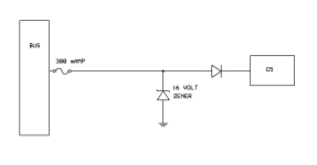
Would splicing a grounded Zener diode with an appropriate breakthrough voltage to the power input of the G5 provide overvoltage protection that would pop the breaker if there was an OV event and save my G5?

I also have an electronically dependent avionics system and I fly IFR. My battery backed up G5 is my last option to get out of the clouds.
If I have an OV event that isn't stopped by the regulator, then I could lose all of avionics, including my G5, and have a dead panel in the clouds and a really bad day.
Would splicing a grounded Zener diode with an appropriate breakthrough voltage to the power input of the G5 provide overvoltage protection that would pop the breaker if there was an OV event and save my G5?


")

