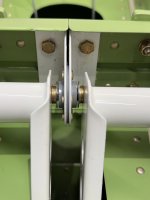
Hello – I’m new to the forum (but not aviation) having bought 2/3 share of a 2012 RV-7A. I’ve been reading info on Vans Airforce for several years, but this is my first time asking for help. As I was doing my walkaround last week, for some reason I pushed one side of the elevator in one direction, and the other in the opposite direction. I expected there to be no relative movement between the left and right elevator horns, but the panels did move differentially by what I estimate to be about ½ inch at the outer edge of the aileron. See video here
. In the video, I have the antisplat gust lock installed, so the elevators are locked. What you see in the video is the free play that I’m asking about. I only show one side of the elevator at a time, but this is the same movement I get when pushing the elevators in opposite directions with the gust lock removed. From looking at the drawings, I have to assume this is coming from the spherical joint at the end of the elevator push rod. I checked another RV-7A at my home airport and found there was not relative motion between the two elevator sides when pushing them in opposite directions. Is a bit of motion normal or is this something that must be corrected before further flight? I have not yet removed the inspection plates in the area, so looking for general thoughts. Much appreciated.

Van's Air Force
You are using an out of date browser. It may not display this or other websites correctly.
You should upgrade or use an alternative browser.
You should upgrade or use an alternative browser.
Unexpected RV-7A elevator differential movement
- Thread starter aerocroft
- Start date

Looks like a inspection is in order. Maybe no fly until you make sure all hardware is in place and tight. Let is know what you find.Hello – I’m new to the forum (but not aviation) having bought 2/3 share of a 2012 RV-7A. I’ve been reading info on Vans Airforce for several years, but this is my first time asking for help. As I was doing my walkaround last week, for some reason I pushed one side of the elevator in one direction, and the other in the opposite direction. I expected there to be no relative movement between the left and right elevator horns, but the panels did move differentially by what I estimate to be about ½ inch at the outer edge of the aileron. See video here. In the video, I have the antisplat gust lock installed, so the elevators are locked. What you see in the video is the free play that I’m asking about. I only show one side of the elevator at a time, but this is the same movement I get when pushing the elevators in opposite directions with the gust lock removed. From looking at the drawings, I have to assume this is coming from the spherical joint at the end of the elevator push rod. I checked another RV-7A at my home airport and found there was not relative motion between the two elevator sides when pushing them in opposite directions. Is a bit of motion normal or is this something that must be corrected before further flight? I have not yet removed the inspection plates in the area, so looking for general thoughts. Much appreciated.

Lower bolt! But you should inspect both.Thanks much. Borrowing pick from Mike Bullock’s page, would you suspect the upper bolt, or lower bolt, or both?View attachment 106492
Thank you - I’m very curious about this topic because I havent seem much discussion of doing this particular test (differential elevator movement). Could this type of motion lead to flutter or more likely the loss of elevator control if the lower bolt were to disconnect?Your decision to do a great pre-flight of your flight controls likely saved your or someone else's life!
More likely it will lead to complete loss of pitch authority/control.Thank you - I’m very curious about this topic because I havent seem much discussion of doing this particular test (differential elevator movement). Could this type of motion lead to flutter or more likely the loss of elevator control if the lower bolt were to disconnect?
I don't think that picture is of his airplane.The upper bolt should have spacer washers in the gap between the elevator horns.
Will grab a photo of mine. Am working on this area now.
That may not solve your issue but it needs sorting
I don't think that picture is of his airplane.
Ah, sorry!
Ignore my post!
I’m glad you posted! Appreciate the picture. Can you also send a picture of the lower bolt?Ah, sorry!
Ignore my post!
This is a great example of a situation where, if doing acro, you’d be happy to have a parachute along. What I typically hear is “you’d never be able to get out anyway”…More likely it will lead to complete loss of pitch authority/control.
Loss of elevator control most likely. If there ever was a Jesus bolt/nut on an RV, this is ONE of them. There are several more.......Thank you - I’m very curious about this topic because I havent seem much discussion of doing this particular test (differential elevator movement). Could this type of motion lead to flutter or more likely the loss of elevator control if the lower bolt were to disconnect?
I’d very much like to have the list of Jesus bolts!Loss of elevator control most likely. If there ever was a Jesus bolt/nut on an RV, this is ONE of them. There are several more.......
The two bolts and especially the bottom (horn) bolt can be quite difficult to shim perfectly. Vans plans mention various washer thicknesses. I suspect the bottom on May be loose or shimmer with a piece of aluminum tubing that compressed. Saved someone's life, you did.
Get this book:I’d very much like to have the list of Jesus bolts!

Maintenance Handbook For Van's RV Aircraft | Aircraft Spruce ®
Maintenance Handbook For Van's RV Aircraft It should be the ultimate reference guide for you or your mechanic to inspect and maintain the aircraft throughout its life.

I’m glad you posted! Appreciate the picture. Can you also send a picture of the lower bolt?
It’s the lower bolt I’m working on now, drilling the holes for the control rod.
Thanks much. Borrowing pick from Mike Bullock’s page, would you suspect the upper bolt, or lower bolt, or both?View attachment 106492
@bullojm1 has been flying for many years and has tons of hours on his plane. I assume this was an early assembly pic and that Mike added the washers later.
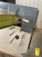
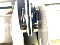
Here is what that top bolt and bearing should look like:

Book ordered - I always enjoy Vic’s articles in EAA so this takes it to the next levelGet this book:
Maintenance Handbook For Van's RV Aircraft | Aircraft Spruce ®
Maintenance Handbook For Van's RV Aircraft It should be the ultimate reference guide for you or your mechanic to inspect and maintain the aircraft throughout its life.www.aircraftspruce.com
View attachment 106507
Yes, this was a very good find and must by fixed before flying again. I would suspect wrong washer shimming on that bottom bolt and most likely worn holes in the horns. I would also suggest buying "Are your Nuts Tight" by Vick Syracuse. I would suggest this to anyone that did not build their RV. Here is an article about the book.Hello – I’m new to the forum (but not aviation) having bought 2/3 share of a 2012 RV-7A. I’ve been reading info on Vans Airforce for several years, but this is my first time asking for help. As I was doing my walkaround last week, for some reason I pushed one side of the elevator in one direction, and the other in the opposite direction. I expected there to be no relative movement between the left and right elevator horns, but the panels did move differentially by what I estimate to be about ½ inch at the outer edge of the aileron. See video here. In the video, I have the antisplat gust lock installed, so the elevators are locked. What you see in the video is the free play that I’m asking about. I only show one side of the elevator at a time, but this is the same movement I get when pushing the elevators in opposite directions with the gust lock removed. From looking at the drawings, I have to assume this is coming from the spherical joint at the end of the elevator push rod. I checked another RV-7A at my home airport and found there was not relative motion between the two elevator sides when pushing them in opposite directions. Is a bit of motion normal or is this something that must be corrected before further flight? I have not yet removed the inspection plates in the area, so looking for general thoughts. Much appreciated.

Book Review: Are Your Nuts Tight? - KITPLANES
Vic Syracuse has written two definitive guides to Experimental Aircraft Pre-Buys and Condition Inspections.
Ordered!Yes, this was a very good find and must by fixed before flying again. I would suspect wrong washer shimming on that bottom bolt and most likely worn holes in the horns. I would also suggest buying "Are your Nuts Tight" by Vick Syracuse. I would suggest this to anyone that did not build their RV. Here is an article about the book.
Book Review: Are Your Nuts Tight? - KITPLANES
Vic Syracuse has written two definitive guides to Experimental Aircraft Pre-Buys and Condition Inspections.www.kitplanes.com
I install the elevators, then use a stack of feeler gauges to determine the spacer required on each side (mic the stack). Then lathe custom large diameter spacers in lieu of the 5702 washer and "stack of washers". Mark "L" and "R". Same for the pushrod. A lot easier to install and more precise.
(castellated nuts are temporary!)

(castellated nuts are temporary!)
I once flew my 6A to flare height using only rudder, throttle, and elevator trim. It was a slow evening at the airport and I had the airspace to myself. I determined I "could" get it down and probably survive, but the plane would likely not be reusable. The last 50 feet was pretty PIO laggy. Try it! it's a fun exercise. (Easier if your trim is not on the stick. My 6A had manual trim.)I will be the first to confess I cannot recall checking for differential movement in my elevators during a pre-flight. Very good suggestion!
If that bolt fell out it would be an exciting ride, that's for sure.
Norman CYYJ
Well Known Member
I sure hope that is not a picture of the finished product!I install the elevators, then use a stack of feeler gauges to determine the spacer required on each side (mic the stack). Then lathe custom large diameter spacers in lieu of the 5702 washer and "stack of washers". Mark "L" and "R". Same for the pushrod. A lot easier to install and more precise.
(castellated nuts are temporary!)
View attachment 106510
Good find. First thing I'm looking at when I go out to my hangar today.Hello – I’m new to the forum (but not aviation) having bought 2/3 share of a 2012 RV-7A. I’ve been reading info on Vans Airforce for several years, but this is my first time asking for help. As I was doing my walkaround last week, for some reason I pushed one side of the elevator in one direction, and the other in the opposite direction. I expected there to be no relative movement between the left and right elevator horns, but the panels did move differentially by what I estimate to be about ½ inch at the outer edge of the aileron. See video here. In the video, I have the antisplat gust lock installed, so the elevators are locked. What you see in the video is the free play that I’m asking about. I only show one side of the elevator at a time, but this is the same movement I get when pushing the elevators in opposite directions with the gust lock removed. From looking at the drawings, I have to assume this is coming from the spherical joint at the end of the elevator push rod. I checked another RV-7A at my home airport and found there was not relative motion between the two elevator sides when pushing them in opposite directions. Is a bit of motion normal or is this something that must be corrected before further flight? I have not yet removed the inspection plates in the area, so looking for general thoughts. Much appreciated.
FYI when I was installing my elevators they weren't even but it wasn't that difficult to remove the one and have the hole welded up. That allowed me to redrill the hole where it was supposed to be. So the hole is easily "movable". If you can an EAA tech counselor to help it should be quite doable.
Good luck
danny
All of them!I’d very much like to have the list of Jesus bolts!
All should be checked for tightness annually.
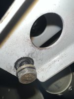
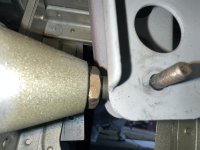
UPDATE: Just went out to the airport and did an inspection. Pictures and a video included. The video here shows the motion on the control rod connection to the elevator horns.
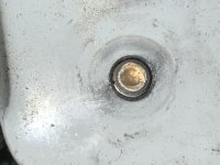
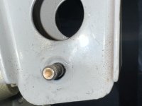
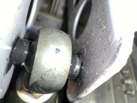
Good news: The upper bolt appears to be assembled as recommended and looks to be OK. I removed the nyloc nut from the lower bolt and the holes in the horns appear to be circular and not worn. The builders had torque-striped the nyloc nut and it had not moved since installation. Rather than washers, the lower spacers appear to be bushings. I tried to tighten the nyloc nut but it bottoms out before it puts any torque on the horns (bolt still turns freely after tightening all the way). Thoughts?
Attachments
UPDATE: Just went out to the airport and did an inspection. Pictures and a video included. The video here shows the motion on the control rod connection to the elevator horns.Good news: The upper bolt appears to be assembled as recommended and looks to be OK. I removed the nyloc nut from the lower bolt and the holes in the horns appear to be circular and not worn. The builders had torque-striped the nyloc nut and it had not moved since installation. Rather than washers, the lower spacers appear to be bushings. I tried to tighten the nyloc nut but it bottoms out before it puts any torque on the horns (bolt still turns freely after tightening all the way). Thoughts?
Replace the bushings with washers! The rod end bearing also looks worn out. I would replace it too while you have it apart! Put in the next size shorter bolt. The ball of the bearing should not be able to spin around the bolt when the assembly is tight.
I think it’s been flying this way for more than 400 hours, about 150 or so with me as pilot. Hadn’t noticed anything odd except for a beat frequency occasionally that I can’t place. Think maybe it’s the elevator “buzzing” but nothing solid to base that on. The aircraft has never been stressed as aerobatics, but I’m planning to begin acro training so i want to review structures that could give me troubleHas it been flying in this condition? What was the handling like?
If the original builder decided to deviate from the plans for the hardware in that location, I would check every nut, bolt and washer in every location from the sticks to the control surfaces. As well as the engine and wing mounts, horizontal and vertical stabilizer.....
Yes as others have said, the bolt must be tight, if the bushing spacing seems good, you might just need another washer on the outboard but nut side, or a shorter bolt as Mel suggests. I can't really tell scale from the pictures on how much thread you have showing, but it does look like there is more shank then there should be (back to the shorter bolt solution), thus the reason why you are not able to tighten up properly.
I'll add a question for my own knowledge and hopefully for the OP as well as they go about fixing this.
Should both the upper and lower bolts be tightened to an airframe torque spec (van's section 5) ? I assume this is the case for these bolts because the movable piece is the rod end bearing in the lower bolt and the upper bearing on the upper bolt, not these bolts, these bolts should not move or rotate, nor should the bushings/washers in line with them. Just so we know how tight is tight.
I assume this is not a "castle nut/bearing type" connection, because the "movable" piece is not in line with these bolts, it's inline with the connection rod or it's inside the upper bearing. And in the case of a "castle nut/bearing type" connection, those are only tight enough for lack of movement, vs torquing it down to an airframe spec.
Just want some confidence in my understanding of the differences in how tight is tight.
Thanks!
Good thought. I know the builders very well and they are very thorough in following drawings/specs in general. It will be interesting to find out if they deviated or if there wasnt sufficient info in the build instructions or drawingsIf the original builder decided to deviate from the plans for the hardware in that location, I would check every nut, bolt and washer in every location from the sticks to the control surfaces. As well as the engine and wing mounts, horizontal and vertical stabilizer.....
Good point! I'm not familiar with the RV-7 plans but the RV-14 plans list the exact hardware to use in every location.It will be interesting to find out if they deviated or if there wasnt sufficient info in the build instructions or drawings
As per plans washers or spacers made from AT6 are acceptable here.
Quite possible the bolt is just loose or too long and torqued to the thread shoulder. Both potentially catastrophic obviously.
Quite possible the bolt is just loose or too long and torqued to the thread shoulder. Both potentially catastrophic obviously.
So in this case, rather than intentionally deviating from the plans, he may have just used the wrong bolt and then didn't notice the bolt was too long when torquing the nut.As per plans washers or spacers made from AT6 are acceptable here.
I'm really glad you shared this post here. I went out and checked for differential play in my elevators this morning after reading this.
Do the differential elevator check on EVERY preflight - just grab the inboard corner of both elevators at the same time and give them a wiggle.Thank you - I’m very curious about this topic because I havent seem much discussion of doing this particular test (differential elevator movement). Could this type of motion lead to flutter or more likely the loss of elevator control if the lower bolt were to disconnect?
It does look like the elevator horns, connecting to the elevator push-rod, may have been drilled a bit too large. And, certainly proper watcher/spacer stack-up and bolt tightness is important here, too. If I recall, that gets match-drilled with an alignment guide block while the horns are clamped together. Should definitely be fixed, but I don't think it's a major safety issue.
Additional thought -- might see if a close tolerance bolt might fit better, assuming it will fit through the rod-end bearing hole.
Additional thought -- might see if a close tolerance bolt might fit better, assuming it will fit through the rod-end bearing hole.
Last edited:
You can achieve the desired torque on a nut without achieving required torque on an overall assembly. This happens when the nut bottoms out on the grip portion of a bolt.
The specified bolt in this assembly is an AN3-14A. While the plans do allow for "spacers" to be made from AT6-058, I think we've learned that 6061-T6 .058"
wall tubing has a tendency to "take a set" over time when loaded axially, and thereby losing the required torque in an assembly. Another example of this is the U-408 wheel/brake flange spacers leading to wheel fairing "wiggle".
So in this case, rather than intentionally deviating from the plans, he may have just used the wrong bolt and then didn't notice the bolt was too long when torquing the nut.
I'm really glad you shared this post here. I went out and checked for differential play in my elevators this morning after reading this
Interesting. I also noticed in Mike Bullock’s post regarding this connection that he found the -14 was too long so he switched to a -13 which he said “was perfect”You can achieve the desired torque on a nut without achieving required torque on an overall assembly. This happens when the nut bottoms out on the grip portion of a bolt.
The specified bolt in this assembly is an AN3-14A. While the plans do allow for "spacers" to be made from AT6-058, I think we've learned that 6061-T6 .058"
wall has a tendency to "take a set" over time, and thereby losing the required torque in an assembly. Another example of this is the U-408 wheel/brake flange spacers leading to wheel fairing "wiggle".
