What's new
Van's Air Force

Don't miss anything! Register now for full access to the definitive RV support community.

To all with experimental built LED Nav lights

Brantel

Well Known Member
To everyone who has rolled their own LED Nav lights, bought a prefab kit from someone or is intending on rolling their own......and plans on or is using one of the constant current drivers by LEDDynamics to power their leds.

These drivers have proven to not work well as a stand alone driver for use in our airplanes due to the fact that they are not designed with proper filtering ect as a stand alone product. The results are that they will trash your aircraft radio with high RFI noise emissions. This will result in audible noise that is hard to squelch and reduction in your radio's sensitivity due to the ANL circuits trying to deal with the increased noise floor.

Bob Nuckolls has agreed to take on the challenge of figuring out what can be done on the cheap and effective to allow us to use these drivers in our planes. He is developing a prototype board/module that will have the driver mounted along with the proper filtering ect. He has access to some test lab that does RFI work and will be doing some lab quality testing on his prototype.

Why? Because these drivers are 95% efficient and voltage dropping/current limiting resistors waste more power than the LED's do combined. Tons of extra heat to deal with and the drivers provide a very controlled constant current to the LED for wide voltage ranges with little to no color or light output change and long life of the LED.

More news to come soon....
 
It's a shame that the drivers are turning out to be such a RFI problem. However, resistors may not be as hopeless as thought.

You can minimize the power dissipated by the resistors by using multiple LEDs in series. Most LED applications I've seen use multiple LEDs anway. If you want to use, say, three red Lux I stars at 350 mA and 3.5V each, you can use a 10 ohm resistor, which will dissipate 1.3W. Wiring the LEDs in series reduces the heat dissipated by the resistor. You can easily find a power resistor that can be heat sinked to the wing for a few bucks.

The downsides are (1) the LEDs are wired in series, and one LED failure (unlikely) or wire/solder joint break (more likely) disables the entire nav light and (2) you now have to dissipate 2w of heat in the aluminum wing. ;)

TODR
 
Last edited:
It's entirely possible to build a constant current switching driver which doesn't spew RFI. I've got my guy at honeywell working on it now.
 
Yea sure it is but most of us don't have a guy at Honeywell at our disposal (your lucky) so we use the cheap off the shelf driver and hope to make it work for us.

Hope you come up with a more elegant solution but make it less than $20, super efficient, light weight, easy to get and integrate into the airplane.
 
Not fully understanding the technology, why is it necessary to use a constant current driver? Rather than 4 of the above mentioned Lux at 3.5v each, in series puts it right at 14v, where the bus would be running most of the time. Is there something about the LED's that make them want to draw too much current? I've got a stoplight full of green led's somewhere around my hanger I need to find and play around with...
 
LED's require a certain amount of forward voltage to get them to do their thing. Once this forward voltage is reached, the current can go up very quickly and destroy the LED.

All LED's have their own unique forward voltage, even the same ones in the same batch may vary. Also, the voltage in our airplanes is far from constant.

If you put four of these in series, they may not even light without the engine running or if your buss voltage sags a little.

Not fully understanding the technology, why is it necessary to use a constant current driver? Rather than 4 of the above mentioned Lux at 3.5v each, in series puts it right at 14v, where the bus would be running most of the time. Is there something about the LED's that make them want to draw too much current? I've got a stoplight full of green led's somewhere around my hanger I need to find and play around with...
 
Last edited:
LED's require a certain amount of forward voltage to get them to do their thing. Once this forward voltage is reached, the current can go up very quickly and destroy the LED.
Yes, LEDs require a certain amount of voltage to light - they are diodes after all. This is called the forward voltage, Vf. If you operate LEDs in series, then the sum of the Vf needs to exceed the supply voltage. Vf for Luxeons are between 3 and 3.5V, depending on the type of emitter.

The constant-current driver gives the LEDs a fixed amount of current and allows the voltage to wander. Vf changes with temperature and each LED is a little different. This is why the constant-current drivers are the best way to go.

A resistor doesn't limit current per se, it just drops the voltage that the LED sees. As the supply voltage and Vf change, the actual current through the LED changes. If you have a fairly stable system, the resistor technique works fine, but it's not ideal.

TODR
 
Last edited:
Yea sure it is but most of us don't have a guy at Honeywell at our disposal (your lucky) so we use the cheap off the shelf driver and hope to make it work for us.

Hope you come up with a more elegant solution but make it less than $20, super efficient, light weight, easy to get and integrate into the airplane.

I can assure you that whatever we come up with will be lightweight, super efficient, and as easy to integrate as the buckpuck is. I can't promise it'll be cheaper than $20, because I seriously doubt we'll have the volume that they do, but we'll probably be able to offer a PCB and a bill of materials for those of you who want to do a little aquiring and soldering in lieu of paying us to make them.


I posted in the other thread asking you which LEDs you had settled on... if I know exactly what you're using, it'll save me some time getting up and running. I'm assuming right now that you are using six K2 stars per side at 500mA apiece. We had sorta planned on running them at 350mA, that's the reference current that allows for full ambient temp range without derating. I'm just somewhat unclear on how to determine if we're meeting the FAR light output requirements.
 
I'm assuming right now that you are using six K2 stars per side at 500mA apiece. We had sorta planned on running them at 350mA, that's the reference current that allows for full ambient temp range without derating. I'm just somewhat unclear on how to determine if we're meeting the FAR light output requirements.
From some earlier work others had done, it looked like three Lux I @ 350mA per side would satisfy the FARs. Six K2 @ 500mA per side ought to be more than plenty.

TODR
 
Great... Design away, we need em!

I am currently running 2 parallel runs of 3 K2 stars in series on each side, 6 total each side. I was using a 1000mA driver which of course due to the current sharing is driving each series run at 500mA.

The K2's are way bright at 500mA and I know others have said the same for them at 350mA so they should be OK at that current as well.

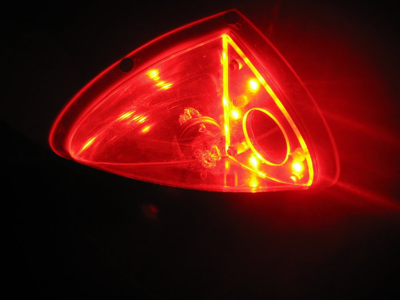
Ouput? Without going to the test lab, we will never know but the results speak for themselves if you ask me:

DSCN5742.jpg


Sounds great offering these as a partial kit. I have no problem spending a little time soldering.

I can assure you that whatever we come up with will be lightweight, super efficient, and as easy to integrate as the buckpuck is. I can't promise it'll be cheaper than $20, because I seriously doubt we'll have the volume that they do, but we'll probably be able to offer a PCB and a bill of materials for those of you who want to do a little aquiring and soldering in lieu of paying us to make them.


I posted in the other thread asking you which LEDs you had settled on... if I know exactly what you're using, it'll save me some time getting up and running. I'm assuming right now that you are using six K2 stars per side at 500mA apiece. We had sorta planned on running them at 350mA, that's the reference current that allows for full ambient temp range without derating. I'm just somewhat unclear on how to determine if we're meeting the FAR light output requirements.
 
Last edited:
alright... we're in the process of selecting a buck converter chip... The design is going to be for 700mA constant current which will drive two strings of three LEDs at 350mA per string. We're going to select higher frequency switchers which will allow us to use smaller, less emissive inductors, and we'll lay it out on a four layer board with power and ground planes on the outside to bury potentially emissive signal traces.
 
4 Lux III's

I'm running 4 Luxeon III stars per side with an oversized resistor. Plenty bright, very cheap, very simple, very quiet, but not super effcient. 350+ hours now and no issues.

Looking forward to seeing what people come up with. Gotta love experimental!

Nav%20Lights%20and%20Kids%20060.jpg
 
caution....

QUOTE: "alright... we're in the process of selecting a buck converter chip... The design is going to be for 700mA constant current which will drive two strings of three LEDs at 350mA per string."

Careful, you can NOT put 2 strings of LEDs in parallel and assume they will split the available current 50/50. They will NOT. Due to tolerance differences and a phenomenon called "thermal runaway" on of the strings will start sucking more current, overheat, suck even more and burn out. then the other string will do exactly the same. Every string must have its own drop power resistor (at the very least) or better yet, its own constant current regulator.
A cheap device called NUD4001 (see this link: http://www.onsemi.com/pub_link/Collateral/NUD4001-D.PDF )
makes a great constant current LED driver with the only limitation of carrying a max of 500 mAmp (I have used at 350 mAmp with good success)
Mouser sells them for little more than 50 cents apiece! Total solid state, no RFI, and they only need one resistor to set up the current limit. Only problem, you need to be pretty good with soldering abilities, and you also would need to get a circuit board.....If someone has the time to do it through PCBexpress, voila'!
Regards,
 
Resistor heat

I'm running 4 Luxeon III stars per side with an oversized resistor. Plenty bright, very cheap, very simple, very quiet, but not super effcient. 350+ hours now and no issues.

Looking forward to seeing what people come up with. Gotta love experimental!

I've also got this setup (thanks to Pete!) and I have to add that I wanted to test the heat-output of the resistor. I let it sit for over an hour with the lights on with no airflow (other than it being in an open wing tip) and the resistors were only warm to the touch.
 
This is a recommended practice per the maker of the K2 stars as long as you put at least 3 in each series run, they are fine. Many of these running this way for many hours of operation. If by chance one series string does die, the full current will flow in the other so in this case, plan for the worse with your CC driver and heatsink and all will be well, the CC source will limit the current.

Careful, you can NOT put 2 strings of LEDs in parallel and assume they will split the available current 50/50. They will NOT. Due to tolerance differences and a phenomenon called "thermal runaway" on of the strings will start sucking more current, overheat, suck even more and burn out. then the other string will do exactly the same. Every string must have its own drop power resistor (at the very least) or better yet, its own constant current regulator.
 
Last edited:
A cheap device called NUD4001 (see this link: http://www.onsemi.com/pub_link/Collateral/NUD4001-D.PDF )
makes a great constant current LED driver with the only limitation of carrying a max of 500 mAmp (I have used at 350 mAmp with good success)...

That is a neat part, I hadn't seen it before. It is linear as you say, no switching, but the packaging looks pretty limiting. If you design for a low system voltage (say 11V), then at voltages of 13.75, the power dissipation goes too high. But if you design for 13.75V, then the thing will shut off if the voltage goes down. Basically it isn't tolerant of variations of input voltage.

I did take a quick look at one of the app notes that looked promising, they used an external transistor to handle most of the power dissipation.
 
Using a linear CC source is guaranteed to have poor efficiency and like others have said, will not tolerate the wide voltage ranges that our airplanes have. Might as well just use a resistor instead of this device.
 
Last edited:
linear supplies are great for low currents, but at high currents they get VERY inefficient VERY quickly. I designed an automotive boost gauge for turbo cars a couple years ago that required 100mA at 5V, supplied off automotive 13.6V... my first iteration used a linear 7805 style SMD regulator, and it COOKED. Redesigned it with a proper buck switcher, and it's MUCH more efficient.
 
*Thread drift alert*

You cooked a 7805 on 100mA with a 13.6 supply?? I'm thinking some other voodoo was going on, I've played with those for years and never had anything even close to that happen.

*We now return you to your regularly scheduled thread*
 
Looks like this thread is bringing out the EE's!

As an EE, I have contemplated designing and rolling my own, but getting a PCB made is not cheap, so I figured I would pay someone who had a kit already and save the time and hassle.

Being a switch mode power supply designer of sorts, I like the power savings they offer vs. linear approaches, but I wonder if that is a major issue here. Sure, we can save energy, but is it that big a deal? Yes, we can get a more constant illumination as changes in battery voltage won't matter (within limits), but how much will the battery voltage on our aircraft vary anyway? We don't care if the battery voltage drops during engine start, and if the alternator goes south during a flight, who cares if the nav light illumination drops a few percent? (One might care if the battery will be drained faster due to the higher loading, but we are not talking about a lot of power and even with simple resistors, the power draw will still be much less than if one had the old style lamps.) Plus, the power resistors will have a much greater reliability than the integrated circuits. And, by using EMI-reducing inductors and bulky capacitors, weight and cost go up even more, plus the final solution will probably require shielded power wiring. Each time the PWM pulses, it will draw a bit of current that can radiate down the entire length of the power wiring, which is long enough to make a great antenna. So, whereas with the linear approach we could ground the system through the airframe and save a bit of weight (though small in absolute terms), we now would have a much heavier shielded cable.

But, if Bob can solve the issues, then I would consider using the system, especially if shielded power wiring can be avoided.
 
Brian,
Thanks for your effort in getting this resolved. I'll wait and see what Bob comes up with. I'm standing by with resistors in hand.

Rocky
 
Agree.

I agree with everyone's comments.
I can simply say that the little device (NUD4001):
1. costs about 60 cents.
2. It can drive three green luxeons in series at 350 mAmps or 4 red luxeons in series at 350 mAmps without any external power transistor or resistor. (3 green and 4 red luxeons in series drop about the same voltage which is around 10 volts. The NUD is left to dissipate the remaining 3-4 volts X .35 A, which is a liitle more than 1.2 watt. No problem there)
3. I have used it in several applications and I think it is fantastic.
4. Certainly is less efficient that a switching power supply, but that simply means that it uses 350 mAmps at 13 volts to drive 3 or 4 leds at 350 mAmps.
5. Generates no noise and needs no shielded wiring.
6. It has been built for this purpose!
I would love for someone to try it out and post a comment here afterwards.
 
Last edited:
I agree with everyone's comments.
I can simply say that the little device (NUD4001):
1. costs about 60 cents.
2. It can drive three green luxeons in series at 350 mAmps or 4 red luxeons in series at 350 mAmps without any external power transistor or resistor. (3 green and 4 red luxeons in series drop about the same voltage which is around 10 volts. The NUD is left to dissipate the remaining 3-4 volts X .35 A, which is a liitle more than 1.2 watt. No problem there)
3. I have used it in several applications and I think it is fantastic.
4. Certainly is less efficient that a switching power supply, but that simply means that it uses 350 mAmps at 13 volts to drive 3 or 4 leds at 350 mAmps.
5. Generates no noise and needs no shielded wiring.
6. It has been built for this purpose!
I would love for someone to try it out and post a comment here afterwards.


Hey, that's a nice little solution... Might have to play with some of those!
 
Looking closer at the NUD4001, I'm not sure it's all that useful. Here's what I came up with based on their datasheet and app notes:

Vin has to be greater than Vf + 1.4V. This device is really just a dressed up linear regulator. I'm using 13.8V as Vin, that's pretty close to a typical float voltage. I'm planning on driving the luxeons at 350mA. The datasheet for the particular LEDs I'm looking at quotes a 3.15Vf @ 350mA. Therefore, pretty much have to drive 2 strings of 3 LEDs each, which will require 2 NUD4001 devices. 3 * 3.15 + 1.4 = 10.85V minimum Vin. Another 3.15V puts us right at 14V, which would mean the whole thing would dropout if the voltage was less than 14V, quite unacceptable.

Ok, so we're looking at 9.45Vf for the 3 leds, which leaves 4.35Vdrop in the regulator at 350mA, which is 1.5W, exceeding the datasheet max of 1.13W.

Well, now we're looking at two ways to get our heat within limits... we either a) reduce our output current to 260mA, which reduces the brightness of the LEDs, or we b) pre-regulate the power to 11-12V. A 7812 would work fine... an LM317 would require a couple more resistors, but allow us to more precisely nail our input voltage to minimize heat in the NUD4001... but all we're really doing is transferring said heat to the pre-regulator.

From there, I'm led to the conclusion of 'why not just skip the NUD4001, use an LM317 to regulate down close to Vf, then a low series resistance to set current?'

I'm going to run the numbers on this possibility, and I'll post back in a few.
 
Alright, just doing a straight LM317 regulator, 1.800K and 270.0R for our setpoint divider gives us 9.583Vout. 3x3.15Vf LEDs is 9.45V, so we need a current set resistor of 0.37R, which will dissipate 46mW, so a 1/4W resistor is fine, no need for a fancy power resistor, and it won't need to be heat sunk. There'll be two of them, one for each 350mA string of 3.

The LM317, however, will. Assuming an upper bound of 14.5V, it's going to be turning 14.5 - 9.5 = 5V @ 700mA = 1.75W directly to heat. The LEDs will be consuming 350mA @ 3.15Vf = 1.1W each, which is 6.6W total... some of that gets turned to light, but a lot of it gets turned to heat... it's already well known that the LEDs need to be heat sunk, but the regulator will need to be INSULATED and heat sunk as well. So, we're using 8.4W of power to put 6.6W through six LEDs... not the most efficient setup ever, but it'll do, and it'll be more consistent than power resistors and just as quiet.

In case anyone's wondering, I'm still looking into the more sophisticated LED switchers, but I'm going to shift my focus to landing lights and strobes. I don't think the solutions I've come up with are cheap enough to warrant using them on position lights, but I'll still keep you guys informed of what we come up with! Right now I'm designing an array of 25 lux Rebels which will have an output of around 3600 lumens. Should be interesting.
 
Even though I seemed to present an argument against switch mode LED drivers, I am not really against them. I have been thinking about this and my biggest concern has been with EMI and the probable need to use shielded power leads. However, if you put the drivers inside the cockpit inside a shielded enclosure and you properly filter the input and output leads, you can probably do away with running shielded wire out to the LEDs themselves. With that idea, I am more excited about using them.

Still, when you factor in the cost of the enclosure and the expense of the filters, it is a higher cost approach and, like I said, even with power hungry linear regulators or resistors, you are still burning up less energy than if you used the old style incandescent lamps.
 
Use a predefined switcher?

Why not use a switcher module like TI's PTN78000a? These are at Digikey for ~ $13. I have not researched this one myself but most 'modules' have all the proper filtering in place. With an adjustable supply, you can always balance the LED drop, along with a fixed resistor to run several strings of LED's without the worry of EMI or excess heat. The possibility of blowing a second serial string like you would with a pure current regulator also goes away.
In the end I see nothing wrong with a little extra heat to raise the reliability in a very low part count device. That said, Anyone using linear regulators should always have the recommended filter cap by the reg! I have seen better than 70MHZ osc on these pins. If using a switcher of your own design be aware that it is a bit of a black art to get them efficient, reliable and quiet.
 
Well, yesterday's hurried back of the envelope work was pretty flawed...

I was focused on keeping the series R as small as possible so as to not have to deal with a big power resistor...

Problem is, that makes it an insufficiently stiff source. This is the entire problem with voltage sources for this application... we need a current source!

Ok so, in my previous example, we've got that 0.37R series resistance which is setting our current... this is predicated on 3.15Vf across each LED, times 3. The way I set up the regulator, we have 0.13V of excess to drop across R, and 0.13/0.37 = 0.350A.

Problem is, even though the luxeons are pretty tight tolerance, the Vf is +/-0.06V. That's up to .18V for 3 modules, and +.18 would put us over Vreg, which would cause dropout. Plus, as the Vf goes to Vreg, current goes to zero.

Further, if the Vf varies on the negative side, if we get -0.06 on all three LEDs, that's -0.18V, which puts the drop across R at 0.31V, which will set our current at 830mA instead of 350mA! This is what I mean about it being insufficiently stiff... ohm's law is V=IR, P=IV. With a sufficiently large R, changes in V don't affect I much, but a lot of current through a large R gives us a large P (power in Watts). Keeping R small so that it doesn't dissipate much power gives us the scenario above, where small changes in V can have a large effect on I.

The only real answer is some sort of current source. More to come... :)
 
Why not use a switcher module like TI's PTN78000a? These are at Digikey for ~ $13. I have not researched this one myself but most 'modules' have all the proper filtering in place. With an adjustable supply, you can always balance the LED drop, along with a fixed resistor to run several strings of LED's without the worry of EMI or excess heat. The possibility of blowing a second serial string like you would with a pure current regulator also goes away.
In the end I see nothing wrong with a little extra heat to raise the reliability in a very low part count device. That said, Anyone using linear regulators should always have the recommended filter cap by the reg! I have seen better than 70MHZ osc on these pins. If using a switcher of your own design be aware that it is a bit of a black art to get them efficient, reliable and quiet.


The BuckPuck driver module people are already using is a "module" and should have all proper filtering in place, yet it's wiping out radios. The TI module may or may not do the same ...

However, that's a voltage source, and we still have the same issues as above, needing series R to manage current through the device. Plus, that particular part number is a positive to negative converter, with an output range of -3 to -15V. Plus, it's not terribly efficient (looks like it'd be around 78% for the range we'd run it, assuming it were positive).
 
The problem with the modules that have built in filtering is that they can only effectively filter the output voltage. Each time the switcher switches, it charges up an output capacitor, basically, that maintains the dc output voltage. This capacitor voltage is drawn down by the load, and so each time the switcher switches, current flows through the power leads to recharge the capacitor. This very brief flow of current can radiate, and the input filter to the power supply can't do much about it - you have to shield the power leads.

Now, if you place the regulators in a shielded box inside the cockpit, you could get by with only shielding the relatively short power lines, and run regular wire out to the LEDs, provided the power supply output is properly filtered.
 
there's ways to filter the input as well, to keep the power on the long wire in the wing from fluctuating. For instance, using an LDO linear reg and a large cap, so the switcher has a "reservoir" to draw from..
 
Then you have to set the regulator voltage a bit below the lowest expected battery voltage and it will increase the power consumption and increase weight and cost. It may be a good compromise, however.
 
Check out Kitplanes

The last few issues of Kitplanes have had a series on LED nav lights (including lumen requirements). After discussing the easy (inefficient) resistor style circuits, Jim Weir presents a $5 solution using a low-power switcher and an external low-cost, high-power transistor. The article also has the schematic.

Alan
RV-9A Wings
N984AW Reserved
 
Been there done that and that article was what pushed Bob into finding a better solution. That driver has many of the pitfalls that we have been discussing here. Most important is that it most likely will have the same negative RFI noise issues that the off the shelf drivers have due to its construction. Emails to Jim on how he planned to deal with the noise have gone unanswered.

The last few issues of Kitplanes have had a series on LED nav lights (including lumen requirements). After discussing the easy (inefficient) resistor style circuits, Jim Weir presents a $5 solution using a low-power switcher and an external low-cost, high-power transistor. The article also has the schematic.

Alan
RV-9A Wings
N984AW Reserved
 
The BuckPuck driver module people are already using is a "module" and should have all proper filtering in place, yet it's wiping out radios. The TI module may or may not do the same ...

However, that's a voltage source, and we still have the same issues as above, needing series R to manage current through the device. Plus, that particular part number is a positive to negative converter, with an output range of -3 to -15V. Plus, it's not terribly efficient (looks like it'd be around 78% for the range we'd run it, assuming it were positive).

With a voltage source a series resistor can be trimmed to match the required current. Yes, LED's are current devices but I assumed that the current would be 'trimmed' when building the module. I could have suggested a slick complex design but I felt a 'trim in assembly' was worth the extra reliability offered by losing the additional current sources. I do not know the 'BuckPuck" but with the name brand modules I have purchased, and following the input filtering, most do very well with EMI.
 
trimming alone isn't enough, because all the devices are going to change voltages due to temperature. The difference in temperature between sitting on a hot ramp and flying at altitude can be enough to swing it from 100mA to 1000mA if the resistance is insufficiently stiff.

A current source is the ONLY way to go for this application.
 
Overthinking?....

Hi Guys,

Gotta wonder here if we might be designing a cruise missile where a rock would work just fine.

I'm not an EE. No Holiday Inn stays. I just try stuff until it works (in areas that are safe and cheap.) I have a total of $40 in electronic parts to make up my left and right nav lights. That includes 4 Lux III lambertian stars and 1 5watt 4.7 Ohm resistor on each side. I deliberately underdrive these using the resistor. I know it is not effcient, but these things are so dang bright they don't need to be run full tilt. If my alternator novas, my buss does go overvolt, and I torch them - I buy new components at less than $25 per side.

I hope we can find a good CC driver that is cheap, effcient, and quiet. Heck, if we do, I will adopt it. But if someone wants a really cheap, quick, dirty, inelegant soution, keep the lowly resistor in the back of your mind. It seems to meet most of the design goals and has some real RV hours behind it.

As my dad used to say, "It ain't pretty, but it works"
 
I think we all here you Pete, Some of these guys just want to make it better and have time to devote to it. Like you, if I had to take the time to do this myself, I would just go with the resisitor but if someone can come up with a simple, light and efficient driver for cheap that won't trash our radio's, why not?

This thread has brought out all the EE's, EE wanabees, part time hobbiest, and people that have no idea what they are talking about...there lurking everywhere it seems.
 
absolutely right on both accounts. There's nothing that says the resistor won't work, but it's inconsistent...

You say you have four luxeon 3's, and they're underdriven. Can we get some details? The datasheet for the 3 in cyan or green gives a Vf of 3.7V at 700mA, which would be considered quite underdriven, considering the green are rated at 1A and the red at 1.4A.

If you have four lux 3's in series at 700mA, that'd be 14.8Vf total for the string. I'd be willing to bet that your alternator rarely does that, and it wouldn't light at all running just on battery.

Since I don't have your actual numbers, I'm gonna play make believe for a bit... If you fed it 13.8V (we'lll assume a sec that's where your voltage regulator sets your float value), and a 4.7R series resistance, we're going to stabilize somewhere in the vicinity of 3.12Vf forward voltage per LED, which gives us 12.48Vf total, leaving us 1.32V across the resistor. 1.32/4.7 = 0.280A current. A reasonable value...

Now, let's say you shut off your alternator, and the battery holds 12.6V... now we have 0.12V across the resistor, which flows 25mA, except now at the lower current, the LEDs have a lower Vf. The bottom end of the curve is 3.05V at 100mA, so we'll go straight down to there... 12.2Vf, .4V across 4.7R is 85mA. 12.6V is on the high side for a battery, and as the battery voltage approaches 12V, the lights are going to get dimmer and dimmer until they shut off completely due to lack of forward bias voltage.
 
Over My head

Hi Ian,

Please don't think I want in any way to limit the innovation - not at all. Just saying that in my case, the caveman approach seems to have worked in a very inelegant way. My wife will confirm this is my approach to most things.......;)

I'll admit I don't understand all the numbers above, but here is a picture of my lovely spokesmodel, Kate and the 4 Lux IIIs in series with the 4.7 Ohm 5 watter.

Nav%20Lights%20and%20Kids%20062.jpg


This is in the hangar with just the battery (no alt) and the Dynon EMS indicating about 12.2V on the main bus.

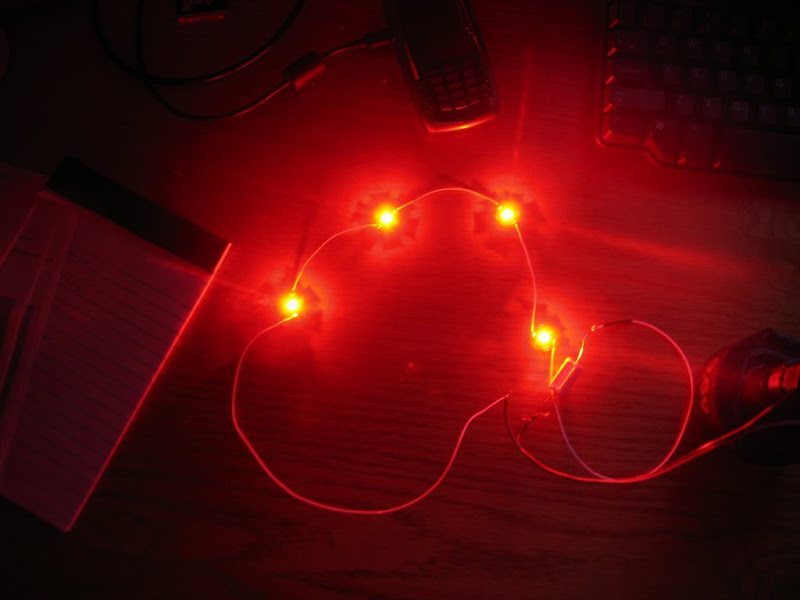
Here are the reds on my desk driven by a 9.6V drill battery:

Nav%20Lights%20and%20Kids%20007.jpg


They are really bright and they will stay that way for at least an hour on the battery - I've never left them on longer than that, but I know they would stay on at least until the main bus hits 9.6V........ I can't answer how it works, but it seems to.
 
Impressive...

The capabilities of this group never cease to amaze me! Being a 2 brain cell Fighter Pilot with alot of night hours on NVG's, I can appreciate lighting, interior or exterior. (Covert IR exterior lights are very cool) But I digress.
I simply bought a set of these when they first came out, bolted them on my Rocket and have amassed 200+ hours on them (30 at night) with no worries. For the non do-it-your-selfer, they work very well...

Smokey
HR2
http://jmhledaircraftlights.blogspot.com/2007/12/aircraft-nav-light-systems-with-cutting.html
 
Last edited:
Trust me Pete, I don't intend to belittle your approach! It works, and that's what's important... I am really curious where you ended up in terms of voltage and current on the LEDs though. The datasheet indicates that it SHOULDN'T work, or at least not well, and yet it does!


Anyway, this is all a worthwhile endeavor for me either way. LED nav lights are straightforward enough that the simple approaches work fine, but I'm also working on a 3600 lumen LED landing light, and I assure you, a resistor isn't enough to handle 60W worth of LEDs ;)
 
Keep us posted

Ian - Absolutely no offense taken. I await your landing light work and will shamlessly copy it if you approve. Agreed the resistor approach will not work there!

LEDs have lots of potential and are getting better and cheaper all the time.
 
I'll certainly keep everyone informed!

I'm noticing more and more people doing APRS... I might oughta jump on that bandwagon when the time comes. I already have a TH-D7A, all I'd need is a serial line from one of my myriad GPS's!
 
You say you have four luxeon 3's, and they're underdriven. Can we get some details? The datasheet for the 3 in cyan or green gives a Vf of 3.7V at 700mA, which would be considered quite underdriven, considering the green are rated at 1A and the red at 1.4A.
Lux IIIs are happy being driven even at 350mA. I've used some Lux III for interior lighting using a 350mA buck puck until I got a 700mA driver that used 120V input. They work very well as wall wash lighting, e.g. "moonlight" illumination in a front-door vaulted entryway.

The Lux III is also very popular with flashlight modders (yes, there are people who mod flashlights) - one popular mod is to make a 2-stage tail cap that uses a 20 ohm resistor to drop the voltage (and thus current) for a "low" beam. High beam is the full 100 lumen goodness. :D

TODR
 
Back
Top