

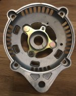
I've been doing a lot of work (testing/experimenting, goofing off) with various alternators of late, and I thought I would share some observations about the ubiquitous Plane Power alternator; Ubiquitous insomuch as it's the alternator that comes with the FWF kit from Van's (ES ALTERNATOR DELUXE). This is the 99-1012 model, circa 2015 and later.

The basis of the unit is the Unipoint ALT-5020. All of the internals (regulator, rectifier, stator, rotor/armature) are Unipoint implementations of Nippondenso parts & designs as follows:
1. The Drive End (DE) brackets and Slip Ring End (SRE) brackets contain NTN bearings (6202LU and 6002LU respectively).
2. DE bracket is a Unipoint casting/machined to clone the Nippondenso unit 101211-2130, 101211-3030 DE bracket.
3. SRE bracket is also a Unipoint casting/machined to clone the Nippondenso unit 101211-2950, 101211-3720 SRE bracket.
* The combination of 2&3 allows the unit to be "re-clocked" to position the B+ terminal, 3 pin connector to a more desirable location.
4. The regulator begins life as a Unipoint YR-662, modified to a -6621 with an overvoltage crowbar circuit on the field circuit. The equivalent regulator is a Nippondenso part 12600-1630 or WAI/Transpo IN257 (w/out overvoltage mod.).
5. The rectifier is a Unipoint REC-644, comprised of 8 - 40/50A diodes. Equivalent to Nippondenso part 21580-3130, -3340 or WAI/Transpo INR718P, INR737, INR724.
6. The brush set is Unipoint BH-634. Equivalent to Nippondenso part 021620-2010 and a dozen others.
7. The stator is the Unipoint equivalent of the Nippondenso part 021100-2860, 50A.
8. The rotor is a bit of a mystery - the nearest Nippondenso equivalent part is 011200-5420, *BUT* the end fans are pitched differently - and I cannot find it in the various catalogs I have access to (ASPL, ElectroLog, Lester).
My impressions -- this isn't a bad unit, or poor quality, or echoing the xenophobic-manosphere -- "cheap Chinese [excrement]...". From an engineering point of view, this alternator suffers from a couple of failure modes that are attributable to the usage model, and I think they can be easily mitigated:
1. Failure of the wiring at the 3 pin plug. The Hartzell provided plug is incomplete; it lacks the strain-relief seals and the pin spacing alignment shim. These parts are available from here:
Sumitomo TS 3 Way Alternator Plug Production Kit, (Toyota # 90980-11349)
https://www.bmotorsports.com/shop/product_info.php/products_id/1704
2. Broken Stator wires under the screw terminals, or inside the DE. I believe this is vibration related - the wire has enough mass and is the right length to resonate at "airplane" frequencies. Copper is very ductile, but it has its limits. Adding a small blob of neutral cure RTV (GE Silicone II, etc.) around the wire penetration points (4) in the SRE should help with this.
3. Failed Regulator. I believe the 6621 is the weakest link, and the crowbar modification doesn't help with reliability (ed: this is why we don't ship motherboards with blue wires, dead bugged parts, and Kapton tape any more...or not a whole lot...). Since heat is the enemy, add a blast tube to bring some of the inlet ram air on to the backside of the SRE. Also, consider substituting a WAI/Transpo IN257 regulator and install a DIY crowbar module at the Alt - Field switch.

4. Failed Diode(s) in Rectifier. Again, heat is an enemy of semiconductors - bring some fresh air on to the back of the alternator. And for those of you worried about water incursion - forget it; the electronics are potted in various materials, resistant to IP67 or beyond.

So, I think I'm done with this obsession for now...My wife can take back her desk and I'm going to go flying...
The basis of the unit is the Unipoint ALT-5020. All of the internals (regulator, rectifier, stator, rotor/armature) are Unipoint implementations of Nippondenso parts & designs as follows:
1. The Drive End (DE) brackets and Slip Ring End (SRE) brackets contain NTN bearings (6202LU and 6002LU respectively).
2. DE bracket is a Unipoint casting/machined to clone the Nippondenso unit 101211-2130, 101211-3030 DE bracket.
3. SRE bracket is also a Unipoint casting/machined to clone the Nippondenso unit 101211-2950, 101211-3720 SRE bracket.
* The combination of 2&3 allows the unit to be "re-clocked" to position the B+ terminal, 3 pin connector to a more desirable location.
4. The regulator begins life as a Unipoint YR-662, modified to a -6621 with an overvoltage crowbar circuit on the field circuit. The equivalent regulator is a Nippondenso part 12600-1630 or WAI/Transpo IN257 (w/out overvoltage mod.).
5. The rectifier is a Unipoint REC-644, comprised of 8 - 40/50A diodes. Equivalent to Nippondenso part 21580-3130, -3340 or WAI/Transpo INR718P, INR737, INR724.
6. The brush set is Unipoint BH-634. Equivalent to Nippondenso part 021620-2010 and a dozen others.
7. The stator is the Unipoint equivalent of the Nippondenso part 021100-2860, 50A.
8. The rotor is a bit of a mystery - the nearest Nippondenso equivalent part is 011200-5420, *BUT* the end fans are pitched differently - and I cannot find it in the various catalogs I have access to (ASPL, ElectroLog, Lester).
My impressions -- this isn't a bad unit, or poor quality, or echoing the xenophobic-manosphere -- "cheap Chinese [excrement]...". From an engineering point of view, this alternator suffers from a couple of failure modes that are attributable to the usage model, and I think they can be easily mitigated:
1. Failure of the wiring at the 3 pin plug. The Hartzell provided plug is incomplete; it lacks the strain-relief seals and the pin spacing alignment shim. These parts are available from here:
Sumitomo TS 3 Way Alternator Plug Production Kit, (Toyota # 90980-11349)
https://www.bmotorsports.com/shop/product_info.php/products_id/1704
2. Broken Stator wires under the screw terminals, or inside the DE. I believe this is vibration related - the wire has enough mass and is the right length to resonate at "airplane" frequencies. Copper is very ductile, but it has its limits. Adding a small blob of neutral cure RTV (GE Silicone II, etc.) around the wire penetration points (4) in the SRE should help with this.
3. Failed Regulator. I believe the 6621 is the weakest link, and the crowbar modification doesn't help with reliability (ed: this is why we don't ship motherboards with blue wires, dead bugged parts, and Kapton tape any more...or not a whole lot...). Since heat is the enemy, add a blast tube to bring some of the inlet ram air on to the backside of the SRE. Also, consider substituting a WAI/Transpo IN257 regulator and install a DIY crowbar module at the Alt - Field switch.
4. Failed Diode(s) in Rectifier. Again, heat is an enemy of semiconductors - bring some fresh air on to the back of the alternator. And for those of you worried about water incursion - forget it; the electronics are potted in various materials, resistant to IP67 or beyond.
So, I think I'm done with this obsession for now...My wife can take back her desk and I'm going to go flying...
")


")


