Van's Air Force

The definitive Van's Aircraft support community! Buying, building or flying an RV? Join our exclusive family of mentors and enthusiasts!

The Baffling Paradox……

Just a quick question: Do I understand correctly you used this resin? Looks like the Heat Distortion Temperature is (only) 290 F. Did you ever had any temperature related problems with the diffuser?

We've talked about HTR212 here previously, as the specs seem high. However, I have not had issues with it at a max temperature around 200F.

Thanks for that. It has the clues you need to use the SW charts referenced earlier.

I just had an opportunity to review that article. It doesn't answer Paul's question about ducts, because the author skips to a conclusion without addressing air side mass flow rate. He merely calculated a need for 670 BTU on the Stewart Warner heat rejection charts. Then he jumped to a pair of 8406R's as the answer.

Just for fun, how does that look?

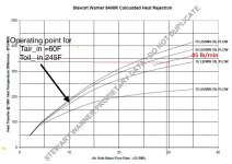
670 / 2 = 335 btu per cooler. At 45 lbs/min oil flow, 335 would require just under 30 lbs/min of air...

Heat Rejection.jpg

...which would require a deltaP of about 9.3" H2O for an 8406R.

Air Side Pressure Drop.jpg

Not likely. Here's a plot of measured static pressures and the resulting deltaP for two RV-8 cowls. Note the airspeed for 9" deltaP. You would need about 170 KTAS.

Static Pressure.jpg
DeltaP.jpg

Something must be wrong with my assumptions

All our assumptions.

Let's start with the manual's "will not exceed" statement for BTUs. It's given as 925/min for the IO-390 (post 41), but "will not exceed" suggests it is a maximum figure. Chris, any chance we can learn how that figure is defined, and under what conditions it is measured or calculated?
 
The chart solves it for the case of (Toil_in -Tair_in) =100F. You have to either solve for Toil_in or assign it a value. What should the maximum temperature be at the oil cooler input? 245?
When we talk about the Lycoming maximum heat rejection case can we assume at sea level at what, 60F? If so everything becomes reasonable.
 

Attachments

  • IMG_0584.jpeg
    IMG_0584.jpeg
    79.6 KB · Views: 2
Last edited:
Just a quick question: Do I understand correctly you used this resin? Looks like the Heat Distortion Temperature is (only) 290 F. Did you ever had any temperature related problems with the diffuser?
While the 290F might be accurate. I cured my diffusers (w/HRT212) up to 300F and they were not drooping in the oven. Each stage of temperature elevation elevates the TG of the final product. All that said, I measured temps under the in the plenum volume and on the glass, but the temps were never that high. A hot shutdown and sealing the inlets was the worst condition. Well under the 290F closer to 200F.
 
Well Paul, the answer is clear as mud. I would certainly have a non engine mounted cooler just a vibration issue for larger flow areas, a structural consideration. Large SMOOTH ducts. Scat bad. Remember Dave Anders doesn't even have a seal between the engine and oil cooler duct pulling air from the plenum volume. just a small gap. Unlike Bob, I could never measure a CHT change from 0-full flow on the oil cooler air flow, but DanH says my PV engine is too tight, no leaks, no squirters You can't really use that as matching air flows between oil and cylinders is a thing rather specific to the engine. Since oil temps must be kept up, a throttle valve will be used anyway so within reason the duct can not be too large. Make the OC duct interior smooth, and a nice inlet radius and etc etc. External OC air could be an option and we have seen a very nice RV6 with that. Not sure you are on the bleeding edge of power and speed, so not sure that is justified for extra 0.2 kts. Also recall Mark F and his 550 opened the inlets ala DanH discoveries, and ran cooler and faster in his Rocket, he was very surprised. Air through the cooler and fins is turbulent throughout the reasonable airspeed range, so the match of mass flows with varying speed is not a worry. I was concerned about that on my tight PV, so went deep on calculations to be sure. You will be using a plenum cover . . . right?

Good luck with the decisions, it shouldn't be hard.
 
Remember Dave Anders doesn't even have a seal between the engine and oil cooler duct pulling air from the plenum volume. just a small gap.

Perhaps not so applicable to Paul's 540 install. Dave is running angle valve cylinders (easier to cool), and $20 says his coefficient of pressure is 0.2 better than the Rocket's standard slot inlet cowl.

Unlike Bob, I could never measure a CHT change from 0-full flow on the oil cooler air flow, but DanH says my PV engine is too tight,

I dunno know about too tight, but it has the most baffle pressure drop of any measured, by far.

Also recall Mark F and his 550 opened the inlets ala DanH discoveries, and ran cooler and faster in his Rocket, he was very surprised.

...and there were those two pretty Rockets at OSH a few years ago.
 
This doesn't directly help you but after the issues with hot cylinders and oil on my previous 7A I decided to do something different: On my IO-390 powered 8A I bolted a 10611R oil cooler to the firewall immediately above the nose gear in my 8A. I fabricated a fiberglass duct and it's fed by a 4" duct from the baffles. It doesn't shake there, oil line routing is simple, moves the CG a tiny bit rearwards helping with the IO-390 weight and balance and having the cowl exit just below it probably doesn't hurt. I have a very hard time getting the oil temps over 198F in summer in Texas. I plan to reduce airflow to the oil cooler as temps are too low at reduced power cruise - below 180F. Photos are during the build. The duct is well secured, protected and things it touches are protected now.
image-58.jpegimage-143.jpegIMG_1405.jpg
 
Something I've not seen discussed here yet is pulling the oil cooling air from the front of the cowl inlets. I've been planning to do this on my Rocket and now on my STC putting a -390 in my Husky. Working on a local Reno racer we measured a 10degree delta from cowl inlet to rear baffle; this led to the idea of making a flat / wide channel-like duct from the top portion on the cowl inlet; run along the inside top of the plenum, diffusing along the way; and feed the oil cooler remotely mounted aft and low. Something to think through anyway.
 
Something I've not seen discussed here yet is pulling the oil cooling air from the front of the cowl inlets. I've been planning to do this on my Rocket and now on my STC putting a -390 in my Husky. Working on a local Reno racer we measured a 10degree delta from cowl inlet to rear baffle; this led to the idea of making a flat / wide channel-like duct from the top portion on the cowl inlet; run along the inside top of the plenum, diffusing along the way; and feed the oil cooler remotely mounted aft and low. Something to think through anyway.

Been there, done that.

Temperature rise between the cowl inlet and oil cooler was 11 to 17 F, depending on conditions over several flights, so I built the insulated duct below. No real change; duct frictional loss seemed to offset lower supply temperature. I removed it.

Duct Layup.jpgFinished Duct.jpg

This is the current setup. Simple radiused entry, rubber supply duct. Outlet ducted to high velocity area of exit bell. I run significant lower cowl pressure, so just dumping in the space there would have reduced deltaP across the cooler. Probably some duct loss here too.

Duct Entry 600w.jpgRubber Duct 600w.jpg

10611 and Ductwork.jpg

Oil Cooler Exit Into Bell.jpg
 
Last edited:
Been there, done that.

Temperature rise between the cowl inlet and oil cooler was 11 to 17 F, depending on conditions over several flights, so I built the insulated duct below. No real change; duct frictional loss seemed to offset lower supply temperature. I removed it.

View attachment 99678View attachment 99679

This is the current setup. Simple radiused entry, rubber supply duct. Outlet ducted to high velocity area of exit bell. I run significant lower cowl pressure, so just dumping in the space there would have reduced deltaP across the cooler. Probably some duct loss here too.

View attachment 99681View attachment 99682

View attachment 99683

View attachment 99684
Nice Dan !!!!!! I admire and respect your thinking and doing. Thank you for sharing and helping me avoid a bunch of time and effort chasing what I thought would be a very reasonable path.
 
Back
Top