What's new
Van's Air Force

Don't miss anything! Register now for full access to the definitive RV support community.

Static port - is this installed correctly?

FlyDave

Member
Hi all,

I got my plane in December of last year and have had issues with winds aloft and, I believe, airspeed (TAS and IAS) and altitude.
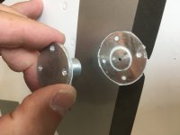
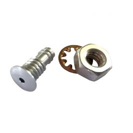
Attached are pics of the static port installation on the left side (darn sloppy work if you ask me!). Right side is the same.
After some internet research including the video below and reading the installation manual, I believe my static ports should be installed as the Cleveland video shows. Is that correct?

Dave

(
)

static port external.jpg


static port internal.jpg
 
Step 1 is remove your static ports and install per manual. Your current installation is likely inducing disturbed airflow.
Step 2 is do no other related maintenance until step 1 is complete, and then test fly.

Another thing to consider after correcting the static port install, is the pitot and static line routing. It’s difficult to tell from the photos, but these need to be routed such that water cannot get trapped in the lines. So no sags, low spots, etc

Hope this helps.
 
Short answer is NO, it is not installed correctly.

They are supposed to be installed through the side skin with only the domed portion in the center, protruding through the skin.
 
Last edited:
The repair may not be as simple as just swapping to the Vans rivet. The hole in the skin is sized for the fitting.
Others may have a solution to filling the hole properly.
Some of us use the fitting but it's riveted and prosealed to the inside. That leaves the outside skin as Vans designed it. Drill the hole, install the static rivet. Then the fittings inside can still be utilized.
 
Last edited:
Pretty much what everybody else said.....NO it is installed wrong. Large flange must be on the inside of the fuselage skin, NOT the outside. Your airspeed readings at any speed are very likely not correct.

Depending on what size hole is already in the side skin, you may need to enlarge it to install the fitting correctly. Use a step dril bit (aka: unibit).....and if you haven't used one or don't feel comfortable doing the drilling.....find a local builder who can assist, and may even have the appropriate size bit.
 
OK, just as I figured.
I believe the back of the static port is the same diameter, or smaller, than the 1/2" part that should protrude (proud) through the fuselage.
I have an A&P that built his RV-6 and maintains a number of others at my home field. I'll work with him to get this resolved and report back on both the structural and flight test results.
Thanks for all your input. This forum and the members are an amazing resource and I'm going to be a paying member (or whatever it's called) this week.

Dave
Do a search for a triangle pattern airspeed calibration test. You can do it before the port correction to confirm the issue, and after to create your ASI calibration sheet.

Good for finding this error!!!
 
OK, just as I figured.
I believe the back of the static port is the same diameter, or smaller, than the 1/2" part that should protrude (proud) through the fuselage.
I have an A&P that built his RV-6 and maintains a number of others at my home field. I'll work with him to get this resolved and report back on both the structural and flight test results.
Thanks for all your input. This forum and the members are an amazing resource and I'm going to be a paying member (or whatever it's called) this week.

Dave
Hopefully the paint wil not get damaged when removing the fitting. Some nylon fishing line or heavy sewing thread may help saw it off carefully. It looks like it is glued on with RTV.

Re. Winds Aloft accuracy, the compass swing can have some affect, so worth checking this if there is an airport compass rose that is convenient.
Yeah, they not only did the job wrong but they were sloppy.
Ahh, good idea for the fishing line or heavy sewing thread!
We have a compass rose at o60 and I did the compass calibration at the compass rose and a 360 in each direction in the air. I'll repeat the 360's in the air once I get the static ports installed correctly.
Pictures to follow.
 
Some nylon fishing line or heavy sewing thread may help saw it off
Yep, that's a good one, assisted by some heat from a (heat) gun.

We had exactly the same situation on the -8, i.e. reversed install on the statics. The speeds were off by > 15kts... 70 KIAS stall speed for an -8 was definitely not right ;)
Installing them ports the right way, as well as curing the leaks in the lines cured the problem.
 
Re. Winds Aloft accuracy, the compass swing can have some affect, so worth checking this if there is an airport compass rose that is convenient.

Paul, the above statement is incorrect. Re-read the paragraphs is the article titled "Math Works" & "Doug Gray’s Method". You use GPS track not compass heading and his method actually helps confirm compass errors or accuracy.

There are links at the bottom of the article that may help explain this a bit better including this one:
Doug Gray's article

Thanks,

Joe
 
Last edited:
Yep, that's a good one, assisted by some heat from a (heat) gun.

We had exactly the same situation on the -8, i.e. reversed install on the statics. The speeds were off by > 15kts... 70 KIAS stall speed for an -8 was definitely not right ;)
Installing them ports the right way, as well as curing the leaks in the lines cured the problem.
Dan,

Are your static ports Dynon? Did you have to modify the hole cut in the fuselage when you installed them the right way?

Dave
 
Hopefully the paint wil not get damaged when removing the fitting. Some nylon fishing line or heavy sewing thread may help saw it off carefully. It looks like it is glued on with RTV.

Re. Winds Aloft accuracy, the compass swing can have some affect, so worth checking this if there is an airport compass rose that is convenient.
If you play guitar, save those strings. The high "E" string is great fir this kind of stuff.
 
You might want to check your battery cable since it’s routed thru a hole and laying against the sharp metal edge.
IMG_1409.png
 
Learning often is by the mistakes we make and they can be expensive. I recommend pulling all inspection panels and getting an experienced builder to go over your airplane. Better yet, get an experienced builder that is an A&P and make it a condition inspection. Simple things like a static system and wire routing Make me wonder what else might be lurking.

Buy Vic’s book Maintenance Handbook For Van’s RV Aircraft. Chapter 10 is pitot static system. The book also has a condition checklist to guide you as you check out your plane for potential issues should you decide to do a thorough going over of your plane and will come in handy later on.
 
get an experienced builder that is an A&P and make it a condition inspection.
Then after that change the A&P every year so new eyes see your plane, at least for the first few years of inspections. Mine was built and after 10 years two different A&P/RV builders missed 12 bolts that were missing in the wing spar area !
 
Paul, the above statement is incorrect. Re-read the paragraphs is the article titled "Math Works" & "Doug Gray’s Method". You use GPS track not compass heading and his method actually helps confirm compass errors or accuracy.

There are links at the bottom of the article that may help explain this a bit better including this one:
Doug Gray's article

Thanks,

Joe
I think he's referring to the displayed winds aloft. Per Dynon that uses GPS, Pitot, static, magnetometer and OAT in the computation.
 
Are your static ports Dynon?
It's been a couple of years now, but the new ones were from Cleaveland, IIRC. As can be seen, the old ones (ACS?) were riveted on the outside of the skin...
Did not have to enlarge the hole, quite the opposite...
 

Attachments

  • IMG_1730.jpeg
    IMG_1730.jpeg
    1.7 MB · Views: 84
Paul, the above statement is incorrect. Re-read the paragraphs is the article titled "Math Works" & "Doug Gray’s Method". You use GPS track not compass heading and his method actually helps confirm compass errors or accuracy.

There are links at the bottom of the article that may help explain this a bit better including this one:
Doug Gray's article

Thanks,

Joe
Joe, I think we are referring to different things.

"Winds Aloft" is the EFIS display of an arrow on the screen that shows wind speed and direction while in flight, e.g. headwind, tailwind or cross-wind. The EFIS calculates it in real time by comparing GPS track and speed versus the aircrafts magnetic heading and air speed. If the magnetometer is not calibrated correctly then the magnetic heading and "Winds Aloft" display may not be inaccurate.

Doug Gray's article is titled "Using GPS to accurately establish True Airspeed (TAS)" so that is something completely different.
 
It's been a couple of years now, but the new ones were from Cleaveland, IIRC. As can be seen, the old ones (ACS?) were riveted on the outside of the skin...
Did not have to enlarge the hole, quite the opposite...
That's what I have except mine are riveted and prosealed inside. The hole was drilled for the Vans rivet then the rivet was installed with a tiny bit of proseal as well. It preserves the Vans aerodynamic design outside and provides a threaded fitting inside.
 
Joe, I think we are referring to different things.

"Winds Aloft" is the EFIS display of an arrow on the screen that shows wind speed and direction while in flight, e.g. headwind, tailwind or cross-wind. The EFIS calculates it in real time by comparing GPS track and speed versus the aircrafts magnetic heading and air speed. If the magnetometer is not calibrated correctly then the magnetic heading and "Winds Aloft" display may not be inaccurate.

Doug Gray's article is titled "Using GPS to accurately establish True Airspeed (TAS)" so that is something completely different.

Got it! My bad. For some reason I thought you were inferring flying a compass heading while in an actual winds aloft crosswind which of course is not what the NTPS spreadsheet has your enter.
 
Learning often is by the mistakes we make and they can be expensive. I recommend pulling all inspection panels and getting an experienced builder to go over your airplane. Better yet, get an experienced builder that is an A&P and make it a condition inspection. Simple things like a static system and wire routing Make me wonder what else might be lurking.

Buy Vic’s book Maintenance Handbook For Van’s RV Aircraft. Chapter 10 is pitot static system. The book also has a condition checklist to guide you as you check out your plane for potential issues should you decide to do a thorough going over of your plane and will come in handy later on.
I had a DAR that built and flies his RV-6 do the prebuy. He was pretty thorough, though I'm not sure he knows how the Dynon static ports are supposed to be installed. He did find a few other things that need to be fixed - nothing of any great magnitude.
On my home field is an RV-6 driver that is A&P and maintains a number of RV's as well as other planes. We're starting my conditional (due this month) next week. So we'll be going through the entire plane as well as installing some upgrades; new "seven stars" landing light, easy exit bar from Anti-Splat and the Flyboy Supertracks.
It's so nice the be an owner again. I've only had certified planes in the past except an Aerotrek A220 and my partner maintained that. I'm having a blast flying this 6A (o-360 & CS prop) and now working on it. Here's a pic of my panel:
20231221_100831.jpg
 
I removed the RTV from both sides and cleaned up the static ports. Avgas helps break down the RTV but it starts to make a mess if you're not careful.
It looks like the original installer somehow cut the holes (instead of drilling them) in the fuselage to put the static ports in from the outside. Pretty sloppy. I cleaned up the burs on the inside and outside but they cut the holes 3/32" larger than the part of the static port that should be "proud" of the fuselage - see the attached picture of the static port taped into the fuselage. I don't think that gap should be left as is to affect the airflow. Should I fill the gap with clear RTV?

static port taped in.jpg
 
yes, it would be best to close that gap with any kind of filler. This is also what we did (the white stuff in the picture above), not sure anymore, but think we used some kind of epoxy paste.
Assuming you will glue those ports from the inside, apply a little piece of tape over the hole of the port, then using enough glue might automatically fill that gap...

Good luck on your condition inspection, the first is usually existing.
 
I’ve been through this with a few earlier vintage RVs that had non standard ports with horrible static position errors.
I think you need to be careful with that filling around the port.
You may find that anything that doesn’t very closely replicate a smooth surface with the protruding “rivet” port will actually produce quite erratic static. Not just inaccurate.
Knowing what I know now, I’d also consider as an option relocating the entire port 1-2” lower with an accurately drilled hole and patch the hole above.
It looks like you have an IFR bird. Poor static performance/accuracy will make your life hard.
 
Last edited:
yes, it would be best to close that gap with any kind of filler. This is also what we did (the white stuff in the picture above), not sure anymore, but think we used some kind of epoxy paste.
Assuming you will glue those ports from the inside, apply a little piece of tape over the hole of the port, then using enough glue might automatically fill that gap...

Good luck on your condition inspection, the first is usually existing.
Yes, I’ll definitely tape over the hole in the port before applying the RTV to fill the gap. I’ll also practice on something else TBD before I do the actual job.
 
I’ve been through this with a few earlier vintage RVs that had non standard ports with horrible static position errors.
I think you need to be careful with that filling around the port.
You may find that anything that doesn’t very closely replicate a smooth surface with the protruding “rivet” port will actually produce quite erratic static. Not just inaccurate.
Knowing what I know now, I’d also consider as an option relocating the entire port 1-2” lower with an accurately drilled hole and patch the hole above.
It looks like you have an IFR bird. Poor static performance/accuracy will make your life hard.
I do fly IFR so I definitely want an accurate pitot/static system. I’ll see what my A&P says this morning about drilling a new appropriate sized hole.
All valuable input; I like options!
 
I did an extensive static port location study for my plane and published in Kitplanes: https://www.kitplanes.com/static-port-location-and-altitude-calibration/
Location and shape are fairly critical. Key here are 1) The Cleveland ports are very good, if installed properly, which here means your gap should in fact be filled carefully, i.e. as if the metal had been cut accurately to just fit the port and 2) If the port is located where Van's says to put it, don't move it, don't make a new hole 2" down. That could introduce errors.
That's exactly how I plan to fill that gap.
I'll check with the A&P on where his plans say the static ports should be located. His is an early model. Was the location of the statics changed in later plans for the 6A?
 
That's exactly how I plan to fill that gap.
I'll check with the A&P on where his plans say the static ports should be located. His is an early model. Was the location of the statics changed in later plans for the 6A?
The static port location for the 6A has not changed, as far as I know. I have the original plans from mid 90's through to current.

The static fitting that is pictured above looks like the fitting that comes in the Dynon installation kit. I'm guessing that there would've been an original static port rivet that was removed (unnecessarily!) and replaced with the new part when the Skyview system was installed.

Another option for the repair is to bond a thin (.025) aluminum patch 1.5-2 inches square on the inside of the hole with JB Weld epoxy (scuff up surfaces first). When the adhesive has hardened fill the outside hole with body filler and sand it smooth/flush. Then drill the new hole of the correct size with a unibit. This is what I would do for a sound repair. Would probably touch up the paint also.
 
I did an extensive static port location study for my plane and published in Kitplanes: https://www.kitplanes.com/static-port-location-and-altitude-calibration/
Location and shape are fairly critical. Key here are 1) The Cleveland ports are very good, if installed properly, which here means your gap should in fact be filled carefully, i.e. as if the metal had been cut accurately to just fit the port and 2) If the port is located where Van's says to put it, don't move it, don't make a new hole 2" down. That could introduce errors.
Great article.
I do agree that moving the port should be a last resort, but doubt 1” vertically (not horizontal) would make much difference.
On my RV7 I originally installed Avery static ports. ( very similar to what appear to be in post 7 - they will be very inaccurate)
I tried many different methods of fixing the position error once I realized the port shape was causing all my issues.
For example I experimented with dams ahead and behind the port. I also shaved down the port to flush with a rivet shaver and then glued the appropriate pop rivet head to the skin.
Both of these methods fixed the position error mostly, but introduced varying degrees of static oscillation which made the AP unusable.
Thankfully the Avery ports were a 1/4 hole and the Cleveland equivalent were a 3/8 hole (I think) so drilling up meant I had a perfect fit for the new ports and all my problems went away.
In summary I think the shape and localized cleanliness of install is a much more critical issue in this particular instance and I can see the OP spending a lot of time getting the shape right with a tricky sheet metal/composite repair that may not deliver a satisfactory result.
In that instance I’d be willing to accept a potentially small position error from moving it down very slightly.
I’m 100% on board striving for as accurate a system as possible as well.
The static port location for the 6A has not changed, as far as I know. I have the original plans from mid 90's through to current.

The static fitting that is pictured above looks like the fitting that comes in the Dynon installation kit. I'm guessing that there would've been an original static port rivet that was removed (unnecessarily!) and replaced with the new part when the Skyview system was installed.

Another option for the repair is to bond a thin (.025) aluminum patch 1.5-2 inches square on the inside of the hole with JB Weld epoxy (scuff up surfaces first). When the adhesive has hardened fill the outside hole with body filler and sand it smooth/flush. Then drill the new hole of the correct size with a unibit. This is what I would do for a sound repair. Would probably touch up the paint also.
I think this patch and re drill is a good plan too - it’s worth trying first.
I’d probably make the hole oversized to say 3/4 too to make sure you have plenty of bonding area for your filler of choice.
 
The static port location for the 6A has not changed, as far as I know. I have the original plans from mid 90's through to current.

The static fitting that is pictured above looks like the fitting that comes in the Dynon installation kit. I'm guessing that there would've been an original static port rivet that was removed (unnecessarily!) and replaced with the new part when the Skyview system was installed.

Another option for the repair is to bond a thin (.025) aluminum patch 1.5-2 inches square on the inside of the hole with JB Weld epoxy (scuff up surfaces first). When the adhesive has hardened fill the outside hole with body filler and sand it smooth/flush. Then drill the new hole of the correct size with a unibit. This is what I would do for a sound repair. Would probably touch up the paint also.

Thinking about this solution I'm wondering if the additional thickness of the patch would prevent the static port from protruding (proud?) far enough out of the fuselage to function as designed. I don't know the thickness of the fuselage skins but this did come to mind.
 
Thinking about this solution I'm wondering if the additional thickness of the patch would prevent the static port from protruding (proud?) far enough out of the fuselage to function as designed. I don't know the thickness of the fuselage skins but this did come to mind.
The fuselage skin is .025 thick and the Dynon fitting "neck" that I measured is .050". So the patch would need to be made from .016 or .020 sheet to allow for the thickness of the adhesive and the paint. The standard pop rivet ports don't sit proud of the skin, other than the natural dome shape

Van's also have available static ports that are threaded and with a bayonet. These are less dependent on the skin being a very specific thickness. It would however require some changes to the connecting tubing on the inside.

 
Back
Top