Van's Air Force

The definitive Van's Aircraft support community! Buying, building or flying an RV? Join our exclusive family of mentors and enthusiasts!

Show me your Firewall mounted oil cooler (RV-7)

Capt John,

Jason Beaver's site has an example of how he did it with FW mounted oil cooler. His whole site is really well documented.
http://jasonbeaver.com/rv7/category/firewall-forward/

I totally forgot about Jason's website! Thank you for the reminder. I really like the oil cooler drain setup he has assembled. He is a very clever guy!

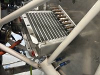
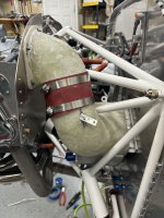
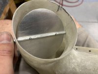
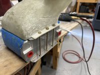
I am not a fan of mounting anything to the engine truss like he did, as typically adel clamps don't age well and slip around over time, especially in oily environments and to have a hefty oil cooler attached to it would be asking for trouble down the road. Besides, I have already installed my RV-10 firewall mounted setup and am proceeding in that direction. However, I am considering Jason's methods for the SCAT tube and butterfly valve!

Thanks again for the heads up!

:) John
 
I found this thread to be extremely helpful when figuring out how I wanted to handle the oil cooler for the 200hp angle valve IO360 on my RV-7. I figured I'd add a report on what I ended up doing.

I knew I wanted to go with a larger cooler mounted on the firewall. I was able to fit the Aero-Classics 10610R 10 row cooler equivalent on the left lower side of my firewall. Given the tight spaces, I ended up constructing a custom 4" duct and diffuser out of fiberglass and with an integral butterfly valve. As you'll see in the pictures, I'm not particularly skilled with fiberglass (all of my experience is from this project), but I am quite pleased with the end result.

Supplies:
  • Aero-Classics HE Series 8001646 (10610R) 10 row oil cooler
  • Airflow Systems oil cooler bolt spacers
  • 4" TCW butterfly valve to deconstruct
  • 4" heavy duty PVC hose
  • Misc hardware
  • Scrap angle
  • Home Depot purple foam + spray adhesive
Notes:
  • This is not pictured, but the front of the oil cooler is supported with a steel bracket to the engine mount.
  • I replaced the hose section in the last picture with a longer section so the hose clamps would be further from the edge.
  • I was able to use the stock Van's hoses for the runs between the engine and cooler.
 

Attachments

  • 000.jpg
    000.jpg
    407.5 KB · Views: 106
  • 005.jpg
    005.jpg
    474.8 KB · Views: 105
  • 004.jpg
    004.jpg
    362.4 KB · Views: 89
  • 003.jpg
    003.jpg
    381.2 KB · Views: 70
  • 002.jpg
    002.jpg
    493.7 KB · Views: 70
  • 001.jpg
    001.jpg
    652.5 KB · Views: 86
David

I like what you have done and especially making your own diffuser. My concern would be that you need to allow for a lot of movement between the baffles and the fixed duct on the cooler. Lycoming’s really shake on startup. I’ve been surprised by baffles hitting the cowls before when I thought there was plenty of clearance.

Regards Peter

Hmmm. I was hoping my short section of hose would account for the movement between the engine and mount/firewall, but admittedly it was not based on any personal experience. I could imagine the hose getting torn if the movement was severe enough.

I could extend the gap section and/or replace the hose with SCAT/SCEET to address this issue.
 
I agree that that setup is going to get beat up in a hurry. The engine moves a surprising amount, especially during startup and shutdown:

 
Thanks for the visual illustration, Matt. That really demonstrates how violent the motion is, particularly in that area.

I removed the thick hose section and replaced with a section of 4" SCEET. It's thinner and more flexible and I preloaded some excess in between the two hose clamps so the two pieces can move in both directions relative to each other. I'm still planning to increase the gap between the two fiberglass sections to increase the clearance, but it seems like the SCEET should give the necessary flexibility. Thoughts?


Thanks for the constructive feedback, really appreciated.
 

Attachments

  • 006.jpg
    006.jpg
    3.2 MB · Views: 11
I removed the thick hose section and replaced with a section of 4" SCEET. It's thinner and more flexible and I preloaded some excess in between the two hose clamps so the two pieces can move in both directions relative to each other. I'm still planning to increase the gap between the two fiberglass sections to increase the clearance, but it seems like the SCEET should give the necessary flexibility. Thoughts?

Just going by TLAR principles, this still seems pretty tight to me. Have you got room to extend the hose further towards the oil cooler, ideally "turning the corner"? Having a bend in the hose would give you a more comfortable amount of slack:

1731445523303.png\
 
Or possibly have the hose attached to the back of the baffle then go through 90 degrees and down to where it attaches above the butterfly valve. That would give you a good amount of flex.
The engine will rotate around the crank. I would think you need to allow for about 3/4 of an inch of movement as a minimum
 
The firewall-mounted 10 row Aero-classics 8000081 in my prior O375-based RV-7A; held oil temps to 180degF thru 10yrs of brutal Texas summers.
Plenums were my crude FG creations. An Avery butterfly valve controlled via a sub-panel mounted pushpull control, throttled the 4" SCAT for cooler weather.
1731456850824.png
 
Back
Top