Van's Air Force

The definitive Van's Aircraft support community! Buying, building or flying an RV? Join our exclusive family of mentors and enthusiasts!

Rv12iS intermittent battery discharge and declining charge voltage

I’m looking for some advice on an electrical issue we’re chasing in a newly acquired RV-12iS.

Summary of the problem:

We’re seeing battery discharge indications associated with lighting loads, along with a slow, progressive degradation in the system’s ability to charge the battery in flight. The behavior is intermittent and inconsistent — occasionally everything looks normal, even with lights on — but the overall trend since purchase has been steadily downward.

Aircraft background / timeline:

We have now flown the aircraft approximately 120 hours in the two months since purchase
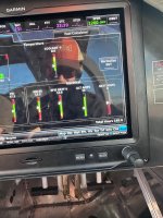
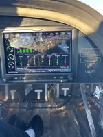
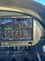
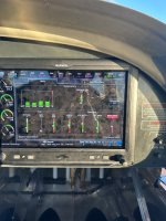
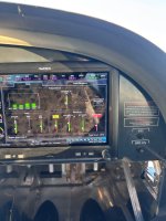
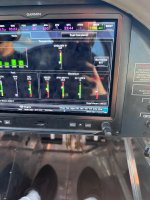
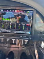
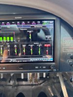
  • Reviewing the aircraft logs, the recorded in-flight battery voltage was consistently 14.0–14.1 volts right up until the day we picked up the airplane
  • When we first began flying it, we were typically seeing 13.8–13.9 volts in flight
  • Over time this has continued to decline, and we are now typically seeing about 13.3 volts in cruise
Notable event prior to pickup:

The night before we picked up the airplane, an issue was being troubleshot where the flap position indicator was not displaying on the G3X. SteinAir was consulted, and wiring work was performed behind the avionics panel during that diagnosis and fix.

Based on the log data and our operational experience, it appears that something may have changed during that troubleshooting, as the battery has never charged the same during flight since that time.

Avionics configuration:

As a general note, the aircraft is equipped with:

Dual Garmin G3X and a Garmin 175

Current symptoms:

The battery discharge behavior is inconsistent and load-dependent, but not in a predictable way
  • Sometimes we can run all exterior lights with no battery discharge indication
  • Other times, running only the strobes will produce a battery discharge indication
  • When a discharge occurs, it does not always correlate with total electrical load
  • Even during flights where the system appears to be charging normally, the battery never seems to recover fully
  • After landing, we use an Optimate 275 charger, which brings the battery up to about 14.1 volts, and the charger indicates the battery itself is healthy
  • The issue is intermittent, with occasional portions of flights where everything appears normal
Rotax shop evaluation:

We had the airplane inspected by a Rotax-certified shop here in Glendale, AZ. They confirmed that everything on the Rotax side, forward of the firewall, is operating as it should, including the charging system components. Based on their assessment, the issue does not appear to be forward of the firewall.

At this point we’re trying to determine whether this is most likely:

An airframe-side charging or distribution issue (wiring, grounds, connectors, fuse blocks, HIC connections, etc.)

A voltage drop or reference issue introduced during avionics wiring work

A poor ground, loose connector, or pin tension problem

Or a known RV-12iS electrical weak point

If anyone has seen similar symptoms or has suggestions on where to start troubleshooting, I’d really appreciate the insight. Specific checks, known failure points, or voltage/current numbers to verify would all be helpful.

Thanks in advance. I used AI to help me craft this post. Hopefully it doesn’t come through too robotic.

Joe
 
This was our flight yesterday (one lap around pattern) with all lights on. Pay attention to ALT amps

Photo1: pre takeoff
Photo 2 : downwind
Photo 3 : crosswind
Photo 4 : base
Photo 5 : final
Photo 6&7 : short final
Photo 8: back on ground
 

Attachments

  • IMG_5365.jpeg
    IMG_5365.jpeg
    2.5 MB · Views: 78
  • IMG_5373.jpeg
    IMG_5373.jpeg
    2.9 MB · Views: 74
  • IMG_5371.jpeg
    IMG_5371.jpeg
    3 MB · Views: 69
  • IMG_5370.jpeg
    IMG_5370.jpeg
    3.1 MB · Views: 65
  • IMG_5369.jpeg
    IMG_5369.jpeg
    2.9 MB · Views: 62
  • IMG_5368.jpeg
    IMG_5368.jpeg
    3.1 MB · Views: 59
  • IMG_5367.jpeg
    IMG_5367.jpeg
    3.5 MB · Views: 62
  • IMG_5366.jpeg
    IMG_5366.jpeg
    3.5 MB · Views: 70
Well, since the B alternator and regulator charge the battery, there is where I would start my search. I know your Rotax shop said everything firewall forwarded was ok, but I’d start with the simple checks and verify no burning on the B regulator connector, which was the basis for a Rotax safety information bulletin. If all looks well there, don’t forget the ground circuit. Verify both sides of the B regulator ground wires are secure. Next verify a solid connection where the B regulator is connected to the AV-60000. If that’s solid, it would then be great if you could monitor the current output of the B regulator to the AV-60000 to see if it’s putting out continuous current.

Those would be my initial checks.
 

Attachments

  • IMG_2870.jpeg
    IMG_2870.jpeg
    341.5 KB · Views: 35
  • IMG_2869.jpeg
    IMG_2869.jpeg
    236.8 KB · Views: 35
  • IMG_2868.jpeg
    IMG_2868.jpeg
    287.2 KB · Views: 35
Looking at the pictures, the total electrical load is about 13 amps
When the alternator output decreases, the battery discharge current increases to maintain 13 amps.
The problem appears to be in the alternator output circuit.
The vast majority of electrical problems are caused by bad connections.
Connectors and terminals are suspect and so are switch contacts.
Bad connection make heat. The temperature of a bad connection goes up when the load is increased.
So turn on all loads and add extra loads if possible to make the temperature of the trouble spot go up and easier to find.
Touch each connector and switch with fingers to find a warm connection.
Or use an Infrared Thermometer.
 
This is all good advice. It sounds like theres a terminal connector or pin that needs to be cleaned up. The grounding is equally as important, and is often overlooked. Theres that ground that Bob pointed out (Fusebox Ground Plate B to brake reservior), there is also one from the firewall (pilot-side) to AV-60000 black terminal, and of course from Battery NEGATIVE to the battery box.

If you're really stumped, you can (in some safe manner) hook up a voltmeter to the fusebox either at the X3 pin, or inside the fusebox on the big 30A fuse inside.. and get a volt reading right after the rectifier -- this would give you a clue as to what the maximum voltage is that you should be seeing along the rest of the bus (though the grey Deutsch Gen B connector is still upstream of this). Its normal to see a small loss (max 0.3v) under load (example: 14.1v, 20A, 10AWG wire, 5 feet -> 0.25v loss)

13.9v - 14.5v is what the manual says is normal.

1766796698839.png
 
Last edited:
Checking for warm connections is one of several troubleshooting methods. You could also use a voltmeter to locate where the voltage is dropping across a bad connection. In some cases it is difficult to connect a voltmeter probe. One trick is to connect a voltmeter alligator clip to a razor blade. Then cut through wire insulation with the razor blade, keeping the insulation slit parallel with the wire to cause minimal damage. Another trick to test a jack and plug type connector is to take the plug and socket apart, then insert a very fine wire strand and plug the connector back together. Then measure the voltage on the fine wire strand. In any case, always test circuits with a load connected.
 
The flight school I rent from had an issue with bad terminals. This was either on the fuse panel or the regulator, I can't remember which.

The terminals were cross threaded, and had increasingly erratic connection to the B generator. It was some kind of press-in threaded insert in a circuit board.
 
We have had this bird in at a certified Rotax shop here in Glendale for over 2 weeks me they can’t figure out, and are telling me that it’s a Vans side issue and are about to give up. Anyone on here near Phoenix that would be able to help us out?
 
Did you (or your A&P) check all four screws on the AV-60000 Power Module? Refer to the Kit Assembly Instructions (KAI) page 42MiS/U-42.

1769547524879.png
 
One potential check to run would be running an independent ground wire from the battery to the fuse box for regulator B.

Last week I was in Rotax heavy maintenance. While discussing things unrelated to your issue the subject of unreliable grounds in the RV-12 came up. The opinion shared there is that while Van's design of the only grounding path through the battery box, firewall, and brake reservoir seems like it should work but also has a high potential, and history, for inconsistent ground paths that can lead to a variety of gremlins.

Low probability that this is your smoking gun, but at this point it sounds like you're looking for anything that might shed some new light.
 
Hi Tony that has been checked as they thought we had a bad circuit board in the fuse box. Bought a new fuse box and that was not the problem. I’m at my wits end right now
 
One other place I've seen a problem similar to this was related to a bad soldersleeve junction installed in the main power feed from the Rotax fusebox to the Van's Power Module. This is installed by Stein when they build the harness. This is where wire K7124 is spliced to Wire K7022.

This splice is not far from the Rotax fusebox and is probably bundled in the group of wires zip tied at the front of the fusebox.

K7124 is the B-generator power feed to the Power module
K7022 comes out of the Rotax fusebox X3 connector on pin #3

See the WH-00136 Schematic, page 11.

1769551329895.png

The splice is probably located somewhere in these yellow marked 10 gauge white wires. This is from KAI 42MiS/U-14.

1769551679239.png

Please be sure to report back to this thread on what you find.
 
Thanks Tony. Just got off the phone with the mechanic and what you just wrote seems to jive with what he found today but he didn’t have a solution as of yet. This power module is what he is finding faulty and its intermittent.
 
Most likely it's not the Power Module itself, but something that is feeding power to the Power Module. In other words, don't shoot the messenger!

Another place I've seen that would cause no power coming out of the Rotax fusebox is the K2 relay inside the Rotax fusebox. This controls the B-regulator output to the aircraft bus, which is output on the X3 connector, pin 3.

1769613518220.png
 
First time I’ve seen the cover off the Rotax fuse box. There’s a lot of fuses in there!
 
Yes there is, and the MMH identifies all of them.

Note: the "A" after the fuse rating stands for AMP, not Lane A.

1769630507919.png
 
Most likely it's not the Power Module itself, but something that is feeding power to the Power Module. In other words, don't shoot the messenger!

Another place I've seen that would cause no power coming out of the Rotax fusebox is the K2 relay inside the Rotax fusebox. This controls the B-regulator output to the aircraft bus, which is output on the X3 connector, pin 3.

View attachment 108416
I chatted with him last night.. I think he said he even replaced the fusebox completely.. So its definitely nothing inside the fusebox, or the regulator. Could be the generator itself.. or that splice that you highlighted earlier or a pin that backed out of the Gen B connector.. Since the issue is in-flight, that also takes the ignition module and HIC module out of the equation too.. so what are we left with? not much.. The whole list (i think):

Generator B, Gen B connector, the splice, wonky Gen B plate-to-brake reservior ground wire, wonky Blue terminal connection, wonky Black terminal-to-pilot-side-firewall connection.


But I recommended he replace that splice regardless of whether it looks bad or not -- its a quick 5 minute job.
 
I spoke to the mechanic for about 45 minutes yesterday explaining how the system works and listening to the things he found during his extensive troubleshooting. He said he changed the Rotax fusebox and the HIC Module. He also tested both the A & B generator outputs and verified the regulator connectors were okay. He said the solder sleeve splice was okay too.

We were reviewing how all the different systems function, particularly the START BUTTON BYPASS function of the Ignition Module/HIC. Once I pointed out that the START/TRIM fuse supplies power to both Arduinos (Power and Ignition Modules) and the cooling fans on the bottom of the instrument panel a light bulb went off in his head.

He said the fuse was good but he noticed the fans were not running every time he had the "no fuel pump" problem. I told him to check the 50 pin connector on the back (front) of the Power Module, pin21. This is the FUSED START POWER wire that powers the Arduino in the Ignition Module, which, of course, is what activates the HIC Module MOSFETS.

Today he said he found the 50 pin connector to be corroded or oxidized and he used some contact cleaner on the male and female ends of the connector a couple times, blew it dry and reassembled. He said this fixed all the problems including the low amp readings.

I would like to hear back from Joe Mckamey if this really solved the problem or not after he flies it for a couple hours.

Rob, has Joe shared any data logs with you? It would be nice to see a couple of before and after logs files.
 
Thanks Tony and Rob for all of your help via text and on the phone. Tony’s phone call to my mechanic was critical. Picked up the airplane today and Colby at Aeromech told me he remembered talking with Tony about 4 years ago with another issue. So much appreciate your time!

I can confirm that it was the 50 pin connector that was the issue. They needed to be cleaned. This was an airplane built by a high school program and not sure what caused this as this started with 22 hours on the airplane. Maybe the connector was handled too much or sat around too long before being installed?

In any case, we flew for 2 hours today and we are charging better than we have seen. We can run all lights and the battery stays up at 13.8-13.9V. We are having fun again!

Thank you Tony Kirk!
 
Thank you for the positive report. I'm glad it all worked out. Goes to show you that remote troubleshooting can sometimes seem like a crap shoot!

Could you please download and send me all the data log files from the G3X (provided you have a data card in the PFD) and add them to a ZIP file.

You can attach the ZIP file to a message here or to a DM them to me so they aren't public.

Thanks!
 
A quick follow up to my post #20 above.

The HIC LED is a valuable diagnostic tool that most people don't understand or utilize. Its function is not documented anywhere except for the Color Code table on page 9 of the WH-0013x-x Wiring Schematic showing the HIC Module details. The mechanic troubleshooting this problem was not aware of its purpose.

If you have a situation where there is no FUSED START POWER (FSP), there will be no START BUTTON BYPASS (SBB) signal from the Ignition Module. In this pre-start condition the HIC Diagnostic LED will be GREEN. Unfortunately, green doesn't mean GO in this situation. I wish I would have thought about this a little more when I added the LED to the HIC Module, I could have made it red in this condition.

Good troubleshooting skills require you to understand how to read a wiring schematic and follow the flow of the circuit from input to output. Fortunately, there is a ton of information on the internet to help you understand schematics. Here is a great example... https://learn.sparkfun.com/tutorials/how-to-read-a-schematic/all

I hope this helps any future troubleshooters!

1769783463636.png

And don't forget, there is a "simplified" overview schematic in the POH. ;)

1769785613985.png
 
Last edited:
Another one of my pet peeves is people who charge their battery when it's not called for. See first post. The EarthX battery installed in our RV-12iS DOESN'T NEED TO BE CHARGED UNLESS IT IS BELOW 13.28 VOLTS!

Please do NOT connect the charger just because this is what you always do (did) with your last airplane, or you are not planning on flying for a month, or because it is cold in your hangar. It is not necessary with the EarthX battery!

Constant charging may cause the automatic "START BUTTON BYPASS" function of the Ignition/HIC Modules to not operate correctly if your battery voltage is too high. See my explanation below.

These notes are from the EarthX FAQ page. https://earthxbatteries.com/faqs/ Also note, the RV-12iS has zero parasitic drain (Unlike Harleys, apparently).

1769870625347.png

1769870967947.png


The automatic "START BUTTON BYPASS" (SBB) function of the Ignition/HIC Modules is the system designed to automatically activate an electronic equivalent of the "Start Power Switch" shown in the Rotax schematic below. The FTS clearly states this functionality depends on the battery being BELOW 13.7 volts!

1769874370061.png

Note: the yellow highlighted text in the FTS is wrong. The ONLY way to re-activate the SBB is cycling the Master Switch.

If your engine stops running in flight the proper way to connect the busses together is by activating the Emergency Backup Battery Switch!


1769875049022.png
This is from the POH.

In most Rotax powered aircraft the pilot must activate (and hold) the momentary "Start Power Switch" to keep the ECU, Lanes and fuel pumps activated until the engine is running.

1769872297328.png

Sorry this is so long, I tend to over-explain the details.

Hopefully this information will encourage people to review their POH and FTS during these long, cold winter days!

PS: Don't charge that EarthX unless it needs it. ;)
 
Back
Top