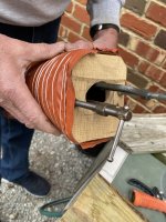
In a post above, I was asked me to follow-up on my "fix". The short version is that I took Dan's advice and decided to try to create a fiberglass duct. In the end, I succeeded.
I maintain that Van's design for the round to square transition on the RV-14 is very poor at best. Note that this issue appears to be for the taildragger only. The nosewheel version seems to be very straight forward as it is "round to round". In addition, there doesn't seem to be a large number of basic IO-390's in taildraggers, most folks appear to have gone to the EXP-119 which has a different cooling configuration eliminating the problem.
First, I tried to design a "duct" for both the baffle (intake) and the round to square transition (outlet). After a few nights of various jigs and measurements, I found that the baffle inlet and the oil cooler inlet were too close vertically to allow for a nice transition from fiberglass to scat back to fiberglass. I opted to make the transition at the oil cooler inlet only.
So, if you have a RV-14 with a standard 5" round to square transition on the scat tubing, here's how I solved the problem.
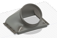
I wanted to be able to use the basic carved foam method as Dan shows above, but unfortunately I wasn't able to duplicate the shape of the oil cooler inlet (square with 45 degree corners) well enough to make me happy. With this in mind I turned to my 3D printer. There is one major problem with using a 3D printed mold for this item. Due to the shape, how would I get the mold out/released once it's cured?
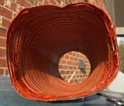
Any mold that would be robust enough to hold it's shape using PLA filament would be difficult to "break" away from the fiberglass. In the end, my son the nerd engineer found that PVA filament is supposed to be water soluble. It's expensve, but I purchased some and made a simple mold to test...it worked. Problem solved.
It took 3 iterations to come up with a shape that worked well. The iterations are shown below.
The first version didn't fit as I punched in the wrong measurement for the corners into Solidworks. However, the layup was valuable to prove that I had the dimensions for the flanges of the box correct. I also downsized the round portion of the outlet to allow for easy insertion into the 5" scat tubing. So, the version 1 wasn't a complete waste of time.
The second version fit like a glove! I was very happy with how everything fit. However, when I put it all together, I found and unacceptable amount of stress on the part and the scat tubing. This was due to the fiberglass transition coming out further from the oil cooler box allowing less length for the scat tubing to make the bend. After some study, I found that angling the intake would reduce or eliminate the stress.
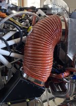
The third version has an angle to reduce stress. It worked. While there's stress in getting the scat tubing and fiberglass "started", once it's over the top of the square flange, it almost snaps into place and stress is minimal. The angle is critical for a proper fit.
The transition allows for good clearance to the motor mount on both the top and bottom and is held in place with nutplates. I painted the it to match the intake box and left the top portion in rough primer to allow just a bit more friction when the scat tubing is installed. A fiberglass "ridge" could easily be put into place to give a mechanical stop for the scat tubing/SS band clamp.
Pictures below: Note, I can print extra molds. If you want one PM me. Cost $95 shipped anywhere in the continental U.S. This is a ONE USE mold as you're going to dissolve/ruin it when it is removed.