So, if you hadn’t noticed, I took a shot at a new method for mounting the red cube in my -9A with a Lycoming YIO-320-D1A with an AvStar fuel injection servo under the heading “Red Cube Install, A new look at an old challenge”, and putting it mildly, it was torn to shreds:
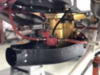
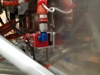
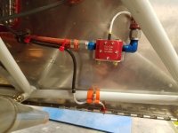
1.) “Adding a bunch of hose length above the engine will result in heating a bunch more fuel while parked. Engine starts after a quick turnaround could be more challenging.” (Scott McDaniels)
2.) “You now have a loop at the highest point for vapor to accumulate.” (Bob Japundza)
3.) “Just wanted to pass on another concern about penetrating the baffle with a hard line at that location. Unless well braced, that spot can be the source of significant vibration, especially if an oil cooler is hanging off the baffles.” (j-red)
4.) “This is evidence enough that there is a lot of vibration induced on this area of the baffling. Putting a hard line between the solidly mounted transducer and the baffle (which has tons of in- service evidence to be always influenced by some level of vibration) is not a good idea.” (Scott McDaniels)
5.) “I'm with Scott regarding the excessive hose length and the hard line.” and “Bob's note regarding the loop is valid. Great place to store lots of vapor.” (Dan Horton)
6.) “Clamping anything much heavier than ignition wires or spider lines to the push rod tubes is generally to be avoided. I’m not predicting anything catastrophic here, but the combined mass of the red cube, the steel bracket, and the attached lines is fairly substantial, and one end of this whole assembly appears to be supported by mid-span clamps on the tubes. The tubes are thin aluminum not intended to be structural elements, and are supported at each end by nothing more than a soft plastic washer jammed into bosses on the engine case and cylinder heads.” (Otis Holt)
I was, and remain grateful for the thoughtful feedback provided by everyone above. Thank you.
It also seems that the engine as purchased through Van’s and configured by Lycoming was somewhat out of the ordinary. It’s my fault for not questioning and fixing this right off, but like I said in my previous post, the engine install skills are my biggest weakness in this build, and I didn’t know enough to question what I received:
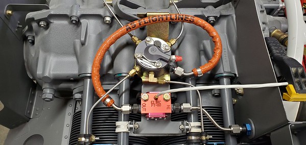
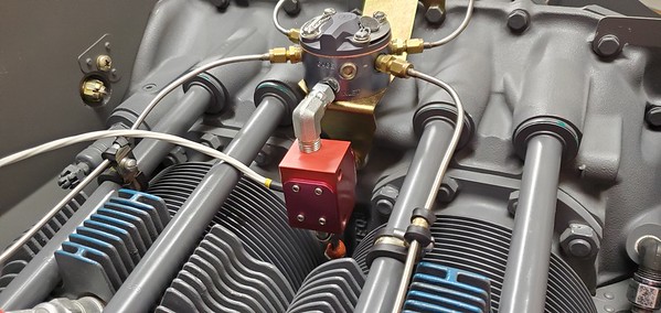
- The fuel distributor was mounted between the #2 and #4 cylinders, when it seems that the more common location for this is between the #1 and #3 cylinders. (BTW, all the IO-320 or IO-360 engines on display at the Lycoming booth at KOSH this year had the divider between #1 and #3).
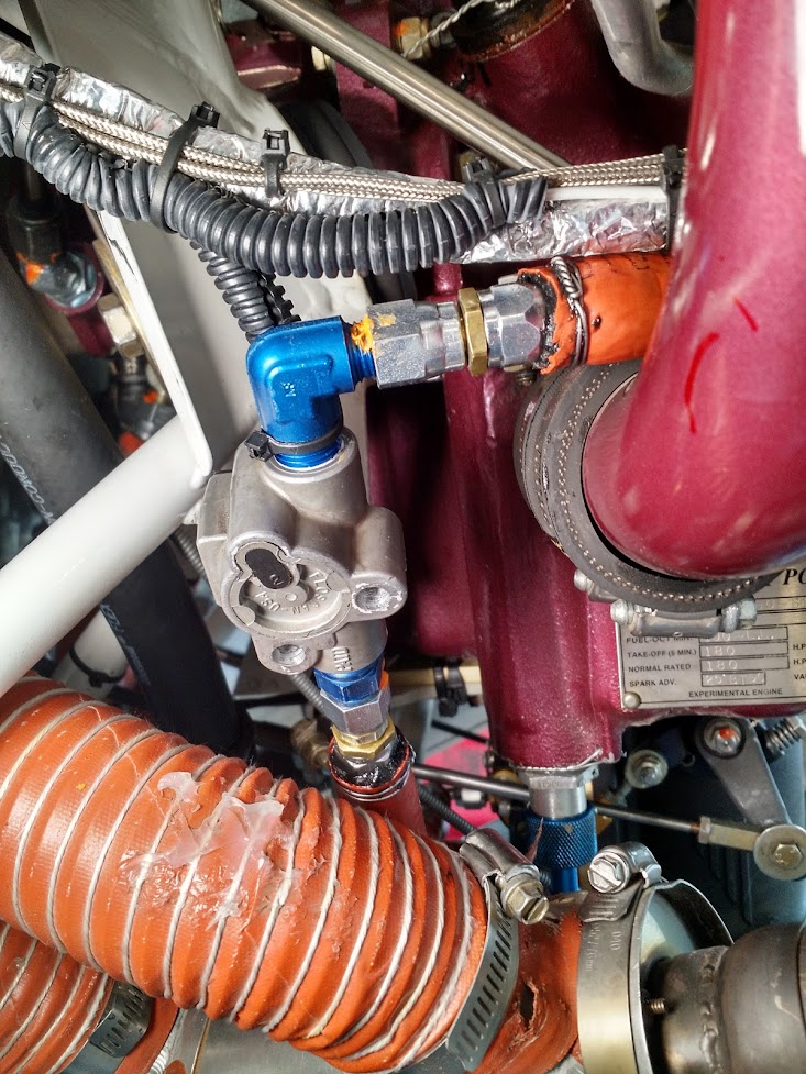
- It also seems that the “IN” port of the distributor is normally positioned perpendicular to the centerline, where mine as positioned at a 45 degree angle to the centerline toward the aft.
This was the first thing I fixed, and it was surprisingly easy to do:
So, where to next? There were a couple of commenters that pointed out EI’s General Placement Recommendations, but it seems that they were referring to old instructions. Thanks to Ed Fleming for posting the link to the updated information, which can be found here: https://buy-ei.com/wp-content/uploads/FT-60-Info-Rev-F.pdf.
From this document I’ve clipped the following:
If the aircraft has a fuel pump(s), the flow transducer MUST be installed downstream of the last fuel pump. Installing the transducer upstream of the fuel pump(s) can cause vapor lock and jumpy/inaccurate readings.
The Red Cube FT-60 has 1/4" NPT ports. Apply thread sealant to fittings, assemble and torque fittings to 8-10 ft. Lbs., DO NOT EXCEED a torque of 12 ft. Lbs. The Red Cube FT-60 should NOT be installed with the wires pointing DOWN (the best situation is with wires pointing UP). Also, the fuel line on the outlet port should not drop down after exiting the transducer. Both of these configurations can trap bubbles in the transducer causing jumpy readings. The inlet port, outlet port and flow direction are marked on the top of the Red Cube FT-60.
In summary, it MUST be installed downstream of the last fuel pump, do not over torque the fittings, and do not install with the wires pointed down.
Also, thanks to Tom Swearengen for his persistence in seeking out the folks at EI during Oshkosh which he summarized in a previous post as, “I was able to talk to EI at Oshkosh. Actually quite pleasant, and some useful information. Idea is for the transducer to not accumulate any air that may change the flow indications. They did not have any issues with the way we have been installing them at the flow dividers.”
What Tom refers to as “the way we’ve been mounting them” is through the use of a stainless-steel elbow fitting with a male NPT on one end, and a female -4 AN fitting on the other which Tom supplies.
However, a well thought out way to secure the red cube to the engine (so it’s not just left hanging from Tom’s fitting did not exist, and that’s where Dan Horton comes in.
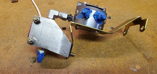
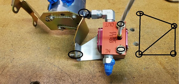
My first attempt at this bracket is shown in the next two pictures. Made from .063? 4130 steel, and again bent on my super cheap HF 18? sheet metal break. Please note that the ?-20 bolt shown holding the divider bracket (Lycoming P/N 75009) and my new bracket gets attached to the existing boss on the engine.
Upon his review, Dan had the following comments, ?The bracket is a great idea, but not really well executed.
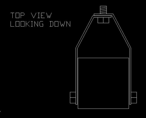
Main issue is its asymmetry...it is one-sided. Assume a vertical load vector due to crankshaft reaction. Part of the load is reacted to the fitting and part to the bracket. Trouble is, the result is a twist, because the bracket is not symmetric to the mass. Not good for the parts, and it tries to unscrew the bolt. The cure is easy enough; a nested bracket for the opposite side (see sketch attached) or a U-shaped bracket (same as sketch, but one piece).
The sketch which Dan makes reference to above is as follows:
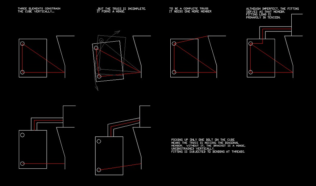
I asked Dan his thoughts about reducing the size of the bracket to aid in fore to aft airflow through the area and he felt this was a non-factor. I also asked about a much smaller bracket only utilizing the lower hole, and he offered the following advice and picture, ?Definitely need two bolts on the cube end of the bracket. The second bolt point effectively makes it a truss. Weak without it.?
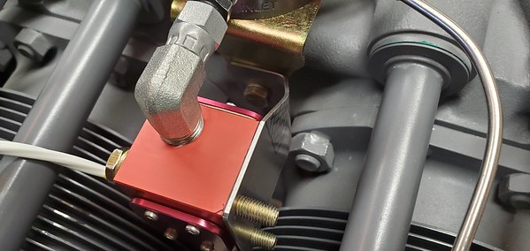
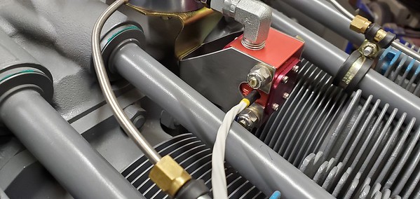
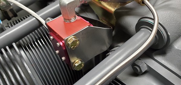
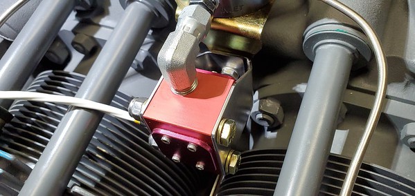
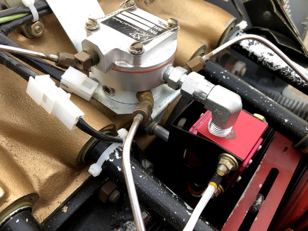
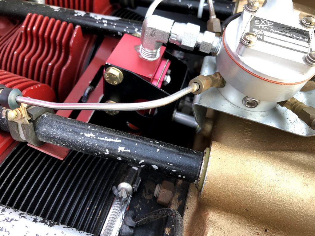
Based on this information I built upon my existing bracket and added a second piece to the aft side of the red cube and here?s where I ended up:
In seeking out Dan?s final approval, he offered the following, ?The attached illustrates why I think it a reasonable plan. I believe the fitting is more than adequate to serve as a tension member.
The side-view truss existed in the prior version, but as noted, it was asymmetric, and that would have subjected both the fitting and the bracket to combined bending and torsion.
If you want to build the Mother of Brackets, simply add a flat plate, sandwiched between the divider body and its bracket. The outboard ends of the plate would be welded to the top edges of your side brackets. The plate would serve as the tension member rather than the fitting. No, I don?t think it is necessary.?
Dan also supplied the following drawing:
So here?s where this ends, a mounting solution for the red cube which:
1. Does not violate any of EI?s installation recommendations
2. Secures the red cube to the engine using a mechanically sound bracket which can be easily made in any builder?s garage shop with minimal tools
3. Can be completed using parts available from Tom Swearengen / TS Flightlines
A couple of final comments:
? For the folks out there with a careful eye, you might notice things like the use of nylon lock nuts, non-spec. hardware, a loose fitting, no paint on the 4130 steel, or the absence of a propeller. Please don?t feel it necessary to point out the painfully obvious, I assure you all that these things will be remedied before my first flight.
? If you don?t like this solution, please step up and offer an alternative. I know this invitation has already been offered, and unfortunately there hasn?t been a response.
? All credit for the engineering of this goes to Dan Horton, who was incredibly generous with his time and knowledge in helping out a complete stranger.
? Tom Swearengen has been a great guy to partner with for the hardware and hoses for this solution. He?s been exceedingly patient with a total rookie, is nearly always available to answer a question, fulfills his orders in a very timely manner, and I?d bet he hasn?t charged me nearly enough for all the parts he?s sent me.
1.) “Adding a bunch of hose length above the engine will result in heating a bunch more fuel while parked. Engine starts after a quick turnaround could be more challenging.” (Scott McDaniels)
2.) “You now have a loop at the highest point for vapor to accumulate.” (Bob Japundza)
3.) “Just wanted to pass on another concern about penetrating the baffle with a hard line at that location. Unless well braced, that spot can be the source of significant vibration, especially if an oil cooler is hanging off the baffles.” (j-red)
4.) “This is evidence enough that there is a lot of vibration induced on this area of the baffling. Putting a hard line between the solidly mounted transducer and the baffle (which has tons of in- service evidence to be always influenced by some level of vibration) is not a good idea.” (Scott McDaniels)
5.) “I'm with Scott regarding the excessive hose length and the hard line.” and “Bob's note regarding the loop is valid. Great place to store lots of vapor.” (Dan Horton)
6.) “Clamping anything much heavier than ignition wires or spider lines to the push rod tubes is generally to be avoided. I’m not predicting anything catastrophic here, but the combined mass of the red cube, the steel bracket, and the attached lines is fairly substantial, and one end of this whole assembly appears to be supported by mid-span clamps on the tubes. The tubes are thin aluminum not intended to be structural elements, and are supported at each end by nothing more than a soft plastic washer jammed into bosses on the engine case and cylinder heads.” (Otis Holt)
I was, and remain grateful for the thoughtful feedback provided by everyone above. Thank you.
It also seems that the engine as purchased through Van’s and configured by Lycoming was somewhat out of the ordinary. It’s my fault for not questioning and fixing this right off, but like I said in my previous post, the engine install skills are my biggest weakness in this build, and I didn’t know enough to question what I received:
- The fuel distributor was mounted between the #2 and #4 cylinders, when it seems that the more common location for this is between the #1 and #3 cylinders. (BTW, all the IO-320 or IO-360 engines on display at the Lycoming booth at KOSH this year had the divider between #1 and #3).
- It also seems that the “IN” port of the distributor is normally positioned perpendicular to the centerline, where mine as positioned at a 45 degree angle to the centerline toward the aft.
This was the first thing I fixed, and it was surprisingly easy to do:
So, where to next? There were a couple of commenters that pointed out EI’s General Placement Recommendations, but it seems that they were referring to old instructions. Thanks to Ed Fleming for posting the link to the updated information, which can be found here: https://buy-ei.com/wp-content/uploads/FT-60-Info-Rev-F.pdf.
From this document I’ve clipped the following:
If the aircraft has a fuel pump(s), the flow transducer MUST be installed downstream of the last fuel pump. Installing the transducer upstream of the fuel pump(s) can cause vapor lock and jumpy/inaccurate readings.
The Red Cube FT-60 has 1/4" NPT ports. Apply thread sealant to fittings, assemble and torque fittings to 8-10 ft. Lbs., DO NOT EXCEED a torque of 12 ft. Lbs. The Red Cube FT-60 should NOT be installed with the wires pointing DOWN (the best situation is with wires pointing UP). Also, the fuel line on the outlet port should not drop down after exiting the transducer. Both of these configurations can trap bubbles in the transducer causing jumpy readings. The inlet port, outlet port and flow direction are marked on the top of the Red Cube FT-60.
In summary, it MUST be installed downstream of the last fuel pump, do not over torque the fittings, and do not install with the wires pointed down.
Also, thanks to Tom Swearengen for his persistence in seeking out the folks at EI during Oshkosh which he summarized in a previous post as, “I was able to talk to EI at Oshkosh. Actually quite pleasant, and some useful information. Idea is for the transducer to not accumulate any air that may change the flow indications. They did not have any issues with the way we have been installing them at the flow dividers.”
What Tom refers to as “the way we’ve been mounting them” is through the use of a stainless-steel elbow fitting with a male NPT on one end, and a female -4 AN fitting on the other which Tom supplies.
However, a well thought out way to secure the red cube to the engine (so it’s not just left hanging from Tom’s fitting did not exist, and that’s where Dan Horton comes in.
My first attempt at this bracket is shown in the next two pictures. Made from .063? 4130 steel, and again bent on my super cheap HF 18? sheet metal break. Please note that the ?-20 bolt shown holding the divider bracket (Lycoming P/N 75009) and my new bracket gets attached to the existing boss on the engine.
Upon his review, Dan had the following comments, ?The bracket is a great idea, but not really well executed.
Main issue is its asymmetry...it is one-sided. Assume a vertical load vector due to crankshaft reaction. Part of the load is reacted to the fitting and part to the bracket. Trouble is, the result is a twist, because the bracket is not symmetric to the mass. Not good for the parts, and it tries to unscrew the bolt. The cure is easy enough; a nested bracket for the opposite side (see sketch attached) or a U-shaped bracket (same as sketch, but one piece).
The sketch which Dan makes reference to above is as follows:
I asked Dan his thoughts about reducing the size of the bracket to aid in fore to aft airflow through the area and he felt this was a non-factor. I also asked about a much smaller bracket only utilizing the lower hole, and he offered the following advice and picture, ?Definitely need two bolts on the cube end of the bracket. The second bolt point effectively makes it a truss. Weak without it.?
Based on this information I built upon my existing bracket and added a second piece to the aft side of the red cube and here?s where I ended up:
In seeking out Dan?s final approval, he offered the following, ?The attached illustrates why I think it a reasonable plan. I believe the fitting is more than adequate to serve as a tension member.
The side-view truss existed in the prior version, but as noted, it was asymmetric, and that would have subjected both the fitting and the bracket to combined bending and torsion.
If you want to build the Mother of Brackets, simply add a flat plate, sandwiched between the divider body and its bracket. The outboard ends of the plate would be welded to the top edges of your side brackets. The plate would serve as the tension member rather than the fitting. No, I don?t think it is necessary.?
Dan also supplied the following drawing:
So here?s where this ends, a mounting solution for the red cube which:
1. Does not violate any of EI?s installation recommendations
2. Secures the red cube to the engine using a mechanically sound bracket which can be easily made in any builder?s garage shop with minimal tools
3. Can be completed using parts available from Tom Swearengen / TS Flightlines
A couple of final comments:
? For the folks out there with a careful eye, you might notice things like the use of nylon lock nuts, non-spec. hardware, a loose fitting, no paint on the 4130 steel, or the absence of a propeller. Please don?t feel it necessary to point out the painfully obvious, I assure you all that these things will be remedied before my first flight.
? If you don?t like this solution, please step up and offer an alternative. I know this invitation has already been offered, and unfortunately there hasn?t been a response.
? All credit for the engineering of this goes to Dan Horton, who was incredibly generous with his time and knowledge in helping out a complete stranger.
? Tom Swearengen has been a great guy to partner with for the hardware and hoses for this solution. He?s been exceedingly patient with a total rookie, is nearly always available to answer a question, fulfills his orders in a very timely manner, and I?d bet he hasn?t charged me nearly enough for all the parts he?s sent me.
Last edited:
")