

mountainride
Well Known Member
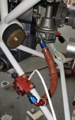
After ~350 hours my red cube gave some erroneous fuel flows varying between 5 and 18 gph on the last flight. It seemed to work properly later in the flight but I assume its at the end of its life. I am trying to figure out how to better protect from heat in the standard RV-14 location on the intake tubes. TS Flightlines has a relocation kit to mount on the engine frame but I was hoping to just swap it out with my existing fuel hoses. I created a heat shield out of scape aluminum but am not really sure if this will help or possibly make it even worse. I was going to put some stick on refective heat shield on top. What is the correct thermo evaluation of my solution?


")


")

 - I'm forgetting about the engine driven fuel pump because my mind is all on the boost pump right now. Hah, thanks! I knew there was a reason!
