Untainted123
Well Known Member
Anyone recognize or have a possible wiring diagram for this arrangement? It's coupled with a PSE PM1000II intercom.


Or - if you have some fine soldering skills, you can build your own AP-60 or similar for $2 in electronic parts. All the costs are for connectors, etc.You could buy and wire a flightdata simple audio mixer AP- 60 ( a few hundred dollars) . You can input all radios, alarms etc and have one out put to your PS Eng. intercom and jus have switch on the PTT to select which radio youwant to transmit on.. Jeff
Unfortunately I don't have the plane anymore, or I would just take it apart and see. I had hoped it was some common wiring that people did back in the day and had a schematic for, because I kind of liked the arrangement, and wanted to see about duplicating it in another plane, without buying a complete ($$) audio panel to add a 2nd comm.WAG without more info...
comm1/comm2 switch is routing ptt switch to either radio
both/auto implies a home made circuit due to the "auto"
check back of the switches to see where the wires go- hopefully you have a tip up canopy to make that easy to do.")
This really isn't the same thing, I don't want to have to turn up and down radio volumes.You could buy and wire a flightdata simple audio mixer AP- 60 ( a few hundred dollars) . You can input all radios, alarms etc and have one out put to your PS Eng. intercom and jus have switch on the PTT to select which radio youwant to transmit on.. Jeff
What is the "this", this switch arrangement? Or one of the other suggestions.I did this on two planes
One way is for the right switch to be 3 pole, double throw, where the extra pole switches between the receivers’ audio outputs. The left switch is just a 1 pole, one throw switch. In ‘off’ the switch is open, this is the ‘auto’ position. On ‘both’ the switch is closed and shorts the two receiver audio outputs lines together. Put an 330 ohm resistor in each audio output line, so the two receivers don’t fight each other.This arrangement was nice because of the "Both/Auto" switch, which is the part I am most curious about. The TX1/TX2 seems straightforward (switch the Mic/PTT), as BobTurner says, but I am wondering how the TX switch is wired to the Both/Auto switch so that it "follows" the TX switch...
If I understand correctly:One way is for the right switch to be 3 pole, double throw, where the extra pole switches between the receivers’ audio outputs. The left switch is just a 1 pole, one throw switch. In ‘off’ the switch is open, this is the ‘auto’ position. On ‘both’ the switch is closed and shorts the two receiver audio outputs lines together. Put an 330 ohm resistor in each audio output line, so the two receivers don’t fight each other.

Yes that is the way to wire a poor man's audio panel for two commsIf I understand correctly:
View attachment 89949
Also possible that auto feeds selected com audio out to intercom audio in and both sends the selected com as above and the other to the unswitched audio input of the intercom. This is lossless with no resistance required. Mine is similar, but more elaborate, as i also have option for nav audio. I used the traditional audio input and the unswitched audio inputs for mixing two streams. Most of the pm series have an unswitched input.Or - if you have some fine soldering skills, you can build your own AP-60 or similar for $2 in electronic parts. All the costs are for connectors, etc.
So to answer the OP:
Most likely the switch on the right feeds mike and PTT outputs from the PSE intercom to either radio 1 or 2, as selected (e.g, a double pole, double throw switch).
The left switch either feeds the audio out from both radios to the intercom, or just the radio selected by the right switch (auto).
Corrected version:No, not quite. Move the two 330 ohm resistors to where the words ‘audio out’ are. They keep any backwards going current from seeing a short.

I'm not sure that's right either. You don't want a 330 ohm resistor on your audio output all the time, do you? I think you only want it there when you have both audio signals connected together...Corrected version:
View attachment 89956
I thought the same, thus the original version, but I am not really an audio guy, so I don't know for sure. I would think the first version only needed protection when they are connected together, not all the time like the 2nd version.I'm not sure that's right either. You don't want a 330 ohm resistor on your audio output all the time, do you? I think you only want it there when you have both audio signals connected together...
Larry, can you elaborate on this more? As in, what kind of switches and what goes where?Also possible that auto feeds selected com audio out to intercom audio in and both sends the selected com as above and the other to the unswitched audio input of the intercom. This is lossless with no resistance required. Mine is similar, but more elaborate, as i also have option for nav audio. I used the traditional audio input and the unswitched audio inputs for mixing two streams. Most of the pm series have an unswitched input.
The 330 ohm resistors (I use 150 ohm, but the values are not critical) allow both radios to be heard when the the on/off switch is ON. Otherwise, only the selected radio will be heard. Shorting the two radio Comm outputs directly together is not recommended, although the Garmin SL-40 radios are ok with this.I'm not sure that's right either. You don't want a 330 ohm resistor on your audio output all the time, do you? I think you only want it there when you have both audio signals connected together...
I'm not sure that's right either. You don't want a 330 ohm resistor on your audio output all the time, do you? I think you only want it there when you have both audio signals connected together...
So I learned the reason for having the 330 ohm resistors be inline with the output from the radio is so that the volume is already set when you switch to both, instead of having the volume fade when switching to both. Having them there makes you go ahead and get your volume right when on single (ie Auto) and it stays at the same level when switching to Both. So the correct version is correct.I thought the same, thus the original version, but I am not really an audio guy, so I don't know for sure. I would think the first version only needed protection when they are connected together, not all the time like the 2nd version.
That is correct, which is why I like this arrangement. This arrangement is also useful if your radios don't have a standby (most do these days), you can use Both to monitor the other radio; or if they do have standby, you could in theory monitor 4(!!) conversations.A thought on "Auto" setting... it may just indicate that the transmit switch also controls the Rx. Auto being: if XMT is set COM1, then RX is also COM1. If XMT is set COM2, the RX is also COM2. Which is nice as it avoids needing to flip two switches and reduces chance of transmitting split (i.e. XMT com1, RCV com2) by accident.
This is exactly correct. For me, coming home to LVK, NorCal approach is very busy. Putting the ATIS on the standby frequency it takes 10 minutes to get it all, in little pieces at a time. Putting it on the second radio and listening to both works. Human ear is pretty good at listening to ATIS but switching focus if you hear your call sign on the other tadio.When I had this setup, I would stage up 4 frequencies and roll through them, and rarely used both, EXCEPT the standby on GTR's ducks under the main freq, and sometimes I literally wanted to hear both voices at the same time at the same volume, so I would use Both in those situations.
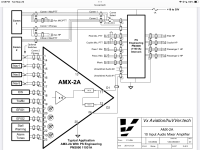
About 20 years ago, I developed the AMX family of audio mixers…. See https://www.huvver.tech/open-source-hardware/Hi.
After about ten year of flying my -8, I desided to add another radio to my A/C.
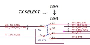
I had to make a kind of Mixer and TX select SW/ So I desined and built my own mixer and added a TX selector SW/
Attached you can find the DWGs.
Feel free to use the schematics.
Hey Vern ( @vlittle ), with MakerPlane ceasing their online store, do you know if someone else is going to pick up your audio mixers? Thanks!
Hope you are enjoying this nice wx Vern.The issue is the cost of shipping, taxes, and tariffs for US destinations. It costs more to ship to US destinations than the cost of building the devices. For the time being, I am supporting business OEM customers who have their own Fedex accounts and will bear the additional costs and paperwork. Customers within Canada are much easier to support, but I am currently out of stock (and out of the country) so will be a few months before I have more inventory.
The audio mixers have been a runaway best seller (hundreds) since I introduced them in 2008. Back then, the cost of shipping to the USA was $2.00. Now, add a couple of zeros to that cost for shipping, paperwork and tariffs! The solution to this is to find a US Supplier willing to pick up the product line, but so far no luck.
Thanks Vern, what about those of us outside the USA? I think shipping to Switzerland will only cost 5 CAD if it's less than 50g if I read the Canada Post website correctly.... Otherwise up to 1kg it's about 30 CAD. I get that shipping is a hassle, even more these days...The issue is the cost of shipping, taxes, and tariffs for US destinations.
As I said "I am currently out of stock (and out of the country) so will be a few months before I have more inventory".Thanks Vern, what about those of us outside the USA? I think shipping to Switzerland will only cost 5 CAD if it's less than 50g if I read the Canada Post website correctly.... Otherwise up to 1kg it's about 30 CAD. I get that shipping is a hassle, even more these days...
Yes I am.... but currently recovering from PickleBall injuries!Hope you are enjoying this nice wx Vern.
That seems to be a common ailment with the seniors around here also.Yes I am.... but currently recovering from PickleBall injuries!
This is not as hard as it seems. Buy some ‘vectorboard’ or other trade name. This is a piece of fiberglass or bakelight which has a large number of pre-drilled holes on 0.1” centers (standard IC spacing). Each hole will have a ring of copper around it. Insert the IC (s) and components from the top side. On the bottom side, bend the leads from the resistors and capacitors to the IC pins where they belong, and solder the leads and pins to the copper circle. With forethought, many of these leads will only need to be bent over to one, or maybe two, nearby holes. There will be a few places where an insulated jumper wire will need to be used. Not nearly as elegant as a PC board, but it can be done.Vern,
Any update on audio mixer availability? I’d like to get my hands on an AMX-4A/B. I can probably scrounge parts and assemble one myself if you can make the PCB artwork (or source) available.
Peter
This is not as hard as it seems. Buy some ‘vectorboard’ or other trade name. This is a piece of fiberglass or bakelight which has a large number of pre-drilled holes on 0.1” centers (standard IC spacing). Each hole will have a ring of copper around it. Insert the IC (s) and components from the top side. On the bottom side, bend the leads from the resistors and capacitors to the IC pins where they belong, and solder the leads and pins to the copper circle. With forethought, many of these leads will only need to be bent over to one, or maybe two, nearby holes. There will be a few places where an insulated jumper wire will need to be used. Not nearly as elegant as a PC board, but it can be done.
I have an AMX-10A. Check your PMThanks Bob,
No doubt I could build a functioning sample this way, but Vern’s elegant design mounts the entire device (fairly densely) inside a 25pin D-sub shell. That’s much of the attraction, but beyond my skill level using perf-board/vectorboard.
Peter