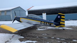
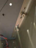
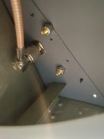
I have an RV-6A, and my GNS-400W antenna has always been placed in the engine compartment, above the magnetos, on a bracket attached to the engine mount:

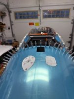
I have occasional loss of GPS signal. I've even had it happen while shooting an IFR approach (VMC luckily). I've read that this is a terrible place for it to be, so maybe that's why. Since I'm doing an engine change right now, I figured it's a good time to move it to the "correct" location.... top fuselage somewhere between the rear window and the vertical stabilizer? But I don't want to go cutting holes unless I'm 100% sure.
Could anyone point me in the right direction on this?
- What is the best / correct location?
- If I'm going to cut a hole, how big is "too big" and where is it unsafe (would compromise the structure)?

")