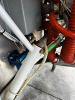
Those brakes lines aren't steel, they're just soft aluminum. When built, it comes in the kit as a roll and the builder cuts off a length, bends it by hand, and flares the ends. It would be pretty easy to cut out the offending section, install a union and then take the new piece all the way to the firewall fitting. You'd need a tubing cutter which is the same one you can buy at Home Depot for copper plumbing line. You'll also need an aviation specific flaring tool. The flaring tool MUST be aviation specific because it makes the flare at a different angle than normal plumbing ones in order to fit aircraft AN hardware. Then bleed the brakes.
If that's not in your skillset, and A&P should be able to knock it out without too much fuss.
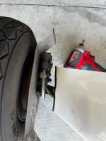
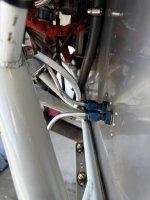
However you do it, you should get rid of those zip ties that are holding the line cinched up against the engine mount and replace them with adel clamps. Dirt and crud will get under those and act like sandpaper. Over time they've been known to wear grooves in the engine mount, which is obviously a big deal.
Also, if it were me I'd get rid of the foam inside the leg fairings. I don't like the idea of filling those up because who knows what sort of corrosion you could have going on underneath on the gear leg that you'd never be able to see or remediate. If you take the foam out, you can do a new brake line start to finish with no splices. If it's just expanding spray foam I think acetone will dissolve it.
edit- I just noticed in one of your pix that if you get rid of the foam, you'll have to add a tab on top of the fairing. Per plan, that faring is positioned and secured by a tab at the top that's held to the gear leg with a radiator hose clamp.