Van's Air Force

The definitive Van's Aircraft support community! Buying, building or flying an RV? Join our exclusive family of mentors and enthusiasts!

Modified Nuckolls Z-12

jjkuzara

Member
I am planning the electrical system in my RV-8A and I am looking for some feedback / sanity check on the electrical system.

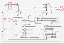
The battery will be in the rear to accommodate the angle valve IO-360 and constant speed prop up front. I am planning a Dynon Skyview system, the vacuum pump will be eliminated to make room for the standby alternator.

I like the idea of a single battery dual alternator system as described in the Bob Nuckolls Z-12 design. I believe the risk of a battery failing can be minimized by using high quality batteries and replacing them religiously.


The Z-12 architecture connects the standby alternator field and regulator overvoltage sense to the main bus. the alternator B lead is connected to the starter contactor hot side. My concern here is that a master contactor failure would take both alternators offline.

I want to move the standby alternator field circuit to the endurance bus and the overvoltage sense to the battery bus. The OV sense goes to the battery bus because under normal operation the diode between the main bus and the endurance bus will cause a 1 to 1.5 volt drop which might not be ideal. I will also move the B lead from the alternator to the battery bus so that the battery can still charge if the master contactor fails.


In normal flight the E-bus alternate feed remains shut off at all times. If the primary alternator fails, the standby alternator will see the drop in voltage on the battery bus and automatically come on. The lamp outputs on the B&C regulators will be connected to inputs on the skyview system to get warning messages. I now have the option to turn on the E-bus alternate feed and shut off the master contactor for immediate load shedding.

If the master contactor dies , the entire electrical system will go dark except for the battery bus. I can restore power to the endurance bus by turning on the E-bus alternate feed which will allow the standby alternator to charge.


Concerns:
The standby alternator regulator overvoltage sense will be always hot on the battery bus, will this cause the battery to drain?
Will the 1 to 1.5 volt difference between the regulator overvoltage sense and the alt field cause a problem?
The standby alternator charge path will be rather long to get to the rear battery. I think this will require 10 gauge at least.
Bob is way smarter that me, if it made sense to design it this way he probably would have, what am I missing?
 

Attachments

  • Main Power Z-12 modified.png
    Main Power Z-12 modified.png
    214.8 KB · Views: 149
Putting a shunt in series with the battery is a bad idea. It will drop voltage that the starter motor needs.
And it adds a few unnecessary failure points.
 
I don't think you need to modify the Z-12 for what you are trying to do, but here are a few suggestions:
My concern here is that a master contactor failure would take both alternators offline.
Shouldn't do. Once the engine is running, the alternator will keep working even if the battery is disconnected.
I will also move the B lead from the alternator to the battery bus so that the battery can still charge if the master contactor fails.
No need if your alternator is still working.
Will the 1 to 1.5 volt difference between the regulator overvoltage sense and the alt field cause a problem?
If you are worried about the voltage drop, you could use a Schottky diode, which will have a voltage drop of roughly 0.3 to 0.5 volts.
 
Would a hall effect sensor be a better idea?
Yes, a hall effect sensor is better. It will not drop voltage and it doesn't have the possible failure points that a shunt has. Not saying that a hall effect sensor can't fail, but if it does, it is not going to disable the electrical system like a shunt could.
Many builders have tried to improve Bob Nuckolls' architecture, but few have. His schematics have withstood peer review.

Hall effect sensors measure amperage so confused why voltage drop is a question. Has anyone seen a shunt stop passing current from the alternator to battery ? Seems a very robust design.

Z-12 uses a shunt on the primary side and a shunt and a Hall effect sensor for the aux bus. Never understood why both are needed unless one wants to use a SB-1 voltage regulator. Seems using 2 LR series regulators and ditch the SB-1 regulator would be simpler.

Z-12 does not place a shunt or hall effect sensor in series with the battery to starter motor.
 
Last edited:
Yes, a hall effect sensor is better. It will not drop voltage and it doesn't have the possible failure points that a shunt has. Not saying that a hall effect sensor can't fail, but if it does, it is not going to disable the electrical system like a shunt could.
Many builders have tried to improve Bob Nuckolls' architecture, but few have. His schematics have withstood peer review.
Hall effect sensors measure amperage so confused why voltage drop is a question. Has anyone seen a shunt stop passing current from the alternator to battery ? Seems a very robust design.
 
I am going back to the drawing board for now. I just learned about the Z-101 architecture which places the second alternator B lead and field circuit on the battery bus like I want. I have been referencing the Aero Electric Connection book which does not Include the Z-101. Here is the link to Bob's website if anyone is unfamiliar. . .

I would plan to eliminate the engine bus as I am not planning an electrically dependent engine.

Many builders have tried to improve Bob Nuckolls' architecture, but few have. His schematics have withstood peer review.
I completely agree, I appreciate the feedback here.
Seems using 2 LR series regulators and ditch the SB-1 regulator would be simpler.
I will probably do this. Bob's Z-101 diagram shows using a generic ford regulator though and I am not completely sure why. Maybe we are not concerned with the crowbar overvoltage protection on the standby alternator?
Z-12 does not place a shunt or hall effect sensor in series with the battery to starter motor.

I added this. Page 7-14 figure 7-13 on The AeroElectric Connection shows using a shunt on the ground side of a battery. Bob states that this is a good way to measure battery current but you need to size up the shunt to 100 amp / 100mV to tolerate the momentary overloading during engine start. I think I will just use a hall effect sensor though based on feedback.
 
Hi OP Justin jjkuzara,
  • Good that you found Z101. Bob Nuckolls proposes it is as reliable as Z14. The colored sections are optional as required.
  • Bob Nuckolls uses the “Ford” regulator for the backup vacuum pad alternator for its low cost.
    • Bob reasons that the chance of two failures in one flight is miniscule. IMO this is fair if one stress tests the backup alternator for significant time in flight in addition to a functional preflight test. This should be done regardless of which backup alternator / regulator / generator is used.
    • I choose B&C LR3 for main and backup because it is adjustable, has OV crowbar, and the cost is small compared to the entire aircraft. OTOH I actually choose Monkworkz MZ-30 generator for backup electrical power source,
    • Bob Nuckolls recommends, if using two B&C regulators, two LR3 regulators versus one LR3 and one SB1 on EAB aircraft. The SB1 was designed due to FAA “bells and whistles” requirements on certified aircraft. Note if one incorporates the Hall Effect current sensor with SB1, it will alarm/flash at 20 A even thought the alternator is capable of 30 A or a little more at Lycoming cruise RPM, be it 410-H, 425-H, 462-H, or legacy SD-20 or SD-20S.
    • I use 14.4 V main and 13.8 V backup regulator settings.
  • A wound field alternator will continue to run if the battery is disconnected but will generally not restart if turned off with no battery present. This makes a failed master contactor a benign failure in flight, as long as one does not turn off the main alternator, and detectable at next preflight.
  • Ideally the electrical power system should allow safe flight in the smoke-in-the-cockpit main master and main alternator off scenario, main buss offline.
  • I and many others choose the Monkwokz MZ-30 permanent magnet generator for backup vacuum pad electrical power source. It puts out 30 A at 1,800 Lycoming rpm and will start and run with no battery present. Note its B lead cannot be connected directly to the battery because is presents a passive load that will drain the battery.
  • In case my electrical power schematic is of interest…. it is a derivation of Z101 but with MZ-30 on the engine bus for EFI+I.
    • The engine bus could be an E bus instead of an engine bus... or no bus at all but the relay needs to be there to disconnect the MZ-30 B lead from the battery due to the MZ-30's passive load.
    • Google Drive link https://drive.google.com/drive/folders/1u6GeZo6pmBWsKykLNVQMvu4o1VEVyP4K
    • It’s in folder 1) A), the pdf called “Elec Power Schem N1921R MZ-30 on engine bus…”.
    • Since you mention rear battery, I have a less detailed draft version for rear battery in folder 1) E) 1), the pdf called “Elec Schem Monkworkz MZ-30 on engine bus Config 5 Rear Battery…”
 
Last edited:
I like the idea of a single battery dual alternator system as described in the Bob Nuckolls Z-12 design. I believe the risk of a battery failing can be minimized by using high quality batteries and replacing them religiously.
The logic behind a dual battery design is not about risk of battery failure. Batteries are the most reliable element in our typical systems. The risk is being able to get this nice reliable power to where you need it when something fails (like a relay, switch, ground, bus connection and such).

No listed is the OP’s design objectives to meet what mission. If this is to be a full up day/night IFR bird, I suggest looking at keeping at least part of the panel up when something fails. Here things like power to the panel that comes via a single master solenoid, or for that matter an avionics buss switch fails (in my opinion) to meet that mission.

On alternators running with no battery. The only one I known of tested to do this is the MonkWorkz. IF you are planning on this as a backup mode I suggest a thoughtful test program to make sure it does what you need..

Side note. As I posted in the past I’m not a fan of the plethora of backup batteries that are now common. I do not consider them to have the endurance or load capability to ensure continued full panel IFR fight for a comfortable 2 hours or so. With a thoughtful two battery design this is achievable without the use of back batteries.

After I found an electrionic igntion back battery with a terminal voltage of 2 volts (12 volt battery) I started to wonder how many of the backup batteries out there are properly maintained, replaced and tested???

Carl
 
I never said that voltage drop was a problem with hall effect sensors.
Didn't mean to offend and always willing to learn but you said "Yes, a hall effect sensor is better. It will not drop voltage" and wanted to understand how a hall effect sensor or even a shunt "drops voltage".
 
No offense taken. A shunt is installed in series with a current carrying wire. That current carrying wire is cut and ring terminals are crimped onto the wire ends. Those crimps are possible failure points. Then the ring terminals are fastened to the shunt with screws or bolts which are two more possible failure points. And the shunt itself can fail open. That is not likely, but I have seen it happen in an industrial application. A shunt has a small amount of resistance that drops voltage. That voltage drop is measured and is displayed on a meter as current.
A hall effect sensor works by measuring the magnetic field around a wire. The wire does not need to be cut. Thus there are no failure points. Of course the hall effect sensor itself can fail. Even if it does fail, the circuit being measured is not affected whatsoever.
Thanks, I have had 6 shunts in 4 airframes FWF and never had a failure, but anything is possible, I guess. Current airframe has 2 shunts (B-leads) and 2 hall effect sensors on my fuel pumps. To summarize the voltage drop you are referencing is supposed to occur and that is how a shunt design works and the complete loss of amp readings could occur in a shunt as well as a hall effect sensor.

It would be interesting to understand failure rates of the hall effect sensors (donuts) vs shunts properly installed FWF.
 
Last edited:
Gotta jump in here with a question: Understanding all of the advantages of Hall effect sensors, why would anyone desire to use shunts? Is there some physical installation reason, or expense? (I guess that may be considered two questions...)
 
Gotta jump in here with a question: Understanding all of the advantages of Hall effect sensors, why would anyone desire to use shunts? Is there some physical installation reason, or expense? (I guess that may be considered two questions...)
Take this thought another step, why have current indication at all?

Ammeters were the choice for cars back in the day as they were cheap and easy. When cheap voltmeters came around ammeters went away. Do you miss having an ammeter in your car?

Are ammeters just another hold over from 1960 Cessna thought?

Voltage provides a much better indication of electrical system health than an ammeter. For me, no shunt or Hall effect sensor in any of the four builds, and I don’t have that heavy wire, big terminal thing on the firewall.

Carl
 
Take this thought another step, why have current indication at all?

(Snip)

Voltage provides a much better indication of electrical system health than an ammeter. For me, no shunt or Hall effect sensor in any of the four builds, and I don’t have that heavy wire, big terminal thing on the firewall.

I agree with you about voltage being the better indicator. One reason for tracking current—an ammeter on the battery helps you understand how fast your battery is being discharged and roughly how much time you have before your battery is dead if your alternator isn’t working right. I don’t see much use in tracking bus or alternator current other than for sake of curiosity since those loads by their nature are variable.
 
Take this thought another step, why have current indication at all?

Ammeters were the choice for cars back in the day as they were cheap and easy. When cheap voltmeters came around ammeters went away. Do you miss having an ammeter in your car?

Are ammeters just another hold over from 1960 Cessna thought?

Voltage provides a much better indication of electrical system health than an ammeter. For me, no shunt or Hall effect sensor in any of the four builds, and I don’t have that heavy wire, big terminal thing on the firewall.

Carl
Maybe it’s a control issue, maybe it’s a trust issue, or maybe OCD, maybe all 3 and I agree voltage can be used to tell if a battery is charging (13.8 to 14.6) volts vs ~13.3 at rest. Possibly depends on battery chemistry. Earth X batteries have almost a linear output from 10% discharge to 90% discharge so if you lose your alternator, it's difficult to tell how much time you have till everything goes dark or worse your engine quits. (electrically dependent engine) By having an ammeter (either shunt or hall effect) on the b leads and the 2 busses (Primary and essential) I get a better understanding how my load shedding is working (simulated alternator failure(s)) and time to find a place to land. Since the shunt can be mounted in line with the ANL fuse on the b-lead it's really does not take up that much space and they are very robust. There have been multiple times when my voltage was lower than normal and nice to see my alternator outputting rated amps. I do not have a preference for shunts over hall effect sensors I've just seen to many installation where builders hang a donut "somewhere" and zip tie it to "something". That is why I worked with a well-known 3-D aviation printing supplier to develop a holder and mount for the "donut".

Obviously most don't need 4-amp sensors on their airframe but 2 or 1 and VPX seems more than worth the peace of mind.

Screenshot 2026-02-13 161046.png
 
Thank you John Bright for the google drive link, I have not had time to dig in and understand all this but I intend to take a closer look before I get too far into building this.

I am coming back with a re-design after studying Bob's Z-101B diagram. I attached my current diagram below. I dropped the engine bus and adapted the clearance delivery / aux bus to be an endurance bus. I moved the main bus feed from the output of the master contactor to the battery post on the starter contactor to save on the long run to the rear battery. I replaced the generic ford regulator with another LR3 because the crowbar overvoltage protection is valuable to me.

I have to do some more thinking as to whether I want the MZ-30 permanent magnet generator.
No listed is the OP’s design objectives to meet what mission. If this is to be a full up day/night IFR bird, I suggest looking at keeping at least part of the panel up when something fails. Here things like power to the panel that comes via a single master solenoid, or for that matter an avionics buss switch fails (in my opinion) to meet that mission.

I intend to fly Night and/or IFR in this aircraft. I want to have confidence in the electrical system to give me options in case of a failure. I want to make sure the gas tank is still the limiting factor on endurance, not the battery.

I am planning two Skyview displays up front. with the primary display fed by the endurance bus and the secondary display fed by the main bus. If the master contactor fails or an electrical issue forces me to turn off the master contactor, I can restore power to critical systems using the E bus relay. The skyview displays will also use the Dynon backup batteries as a last resort and to keep them from powering off during engine start or if I turn the master contactor off before turning on the E-bus alternate feed.

I also intend to place any item I need to safely get to the ground on the Endurance bus. I have not finished planning all the branch circuits but so far this is what I want on the E-bus.

Trim Servos
A/P Servos (debatable but in an emergency I want the help and they are easy to turn off if drawing too much)
Flap Motor
Fuel Pump
Nav/Com 1
Right Mag Bus Feed (Both Mags are Emag P114 with internal magnet and bus feed)
Pitot Heat (on the fence here)
IFR GPS Navigator
Primary Skyview Display

modules powered by the skyview display:
Skyview GPS-2020
ADAHRS 1
ADAHRS 2
Autopilot Panel
EMS-220 Engine monitor

I agree with the discussion about ammeters providing some peace of mind, though I could be talked into dropping the ammeter coming from the alternator B leads in favor of just using the one sensor on the battery ground wire.

Note: I just noticed the E-Bus alternate feed shows the switch in the normally closed position. That is a mistake, should be normally open.
 

Attachments

Last edited:
... The standby alternator regulator overvoltage sense will be always hot on the battery bus, will this cause the battery to drain?...
Yes, either LR3 or SB1 regulator from B&C presents a parasitic load on the sense wire. I measured 22 mA at 12-1/2 V.

One could:
  • Connect sense terminal 3 to bus terminal 6 so the sense terminal would be on the downstream side of the alternator switch.
    • The B&C install instructions as well as Bob Nuckolls council against this because if there are a lot of connections between main bus and regulator, variations in field current cause variations in sense voltage resulting in regulator instability.
    • There are anecdotal reports of terminals 3 and 6 jumped to no ill affect. Perhaps with only a CB and a switch between main bus and regulator said voltage fluctuations are minor. Could be the install instructions are conservative in order to deal with a worst case installation with many connections in series.
    • Z101 jumps connections A and S on the "Ford" regulator and it works. I suppose these connections are equivalent to B&C bus and sense. Correction, ref Post #23.
  • Connect the backup alternator field and sense separately to the CD / essential / endurance bus as is done on the main bus with the main alternator. This has the side effect of raising the B lead voltage by the amount of the diode drop if the CD / essential / endurance bus relay is open. This is not a bad effect if a Schottky diode is used and the regulators are set at say 14.4 V main and 13.5 V backup.
  • Use a separate relay, or separate switch terminals if available, for the backup regulator sense wire.
Note in the case of the Monkworkz MZ-30 PM generator, the B lead presents a parasitic load so it has to be isolated from the battery. In the case of a Z101 derivative with Monkworkz MZ-30, the B lead can be connected to the CD / essential / endurance bus or isolated from the battery by a separate relay.
 
Last edited:
Note in the case of the Monkworkz MZ-30 PM generator, the B lead presents a parasitic load so it has to be isolated from the battery. In the case of a Z101 derivative with Monkworkz MZ-30, the B lead can be connected to the CD / essential / endurance bus or isolated from the battery by a separate relay.

I briefly read through the MZ-30 install manual and this might be my only sticking point with it. For some reason I am not a fan of the B lead for the standby alternator / generator having a relay or contactor between it and the battery. Maybe it is not such a big deal though as it goes through a redundant relay / contactor that can easy be tested during pre-flight. The chances of losing both the main contactor and the E-bus contactor / relay in the same flight are probably near zero.

Besides, at that point it would be impossible to power anything on the E-bus anyway so having the Generator / Alternator B lead connected directly to the battery isn't going to do me any good anyway.

Connect the backup alternator field and sense separately to the CD / essential / endurance bus as is done on the main bus with the main alternator. This has the side effect of raising the B lead voltage by the amount of the diode drop if the CD / essential / endurance bus relay is open. This is not a bad effect if a Schottky diode is used and the regulators are set at say 14.4 V main and 13.8 V backup.

I will probably go with this route if I stick with the standby alternator and B&C regulator.

I think I will end up flying single battery / single alternator during phase 1 testing since we are limited to day VFR / close to home. This will give me plenty of time to think about it. In the meantime I will draw up two versions of my main power diagram while it is fresh in the mind, one with the standby alternator and one with the MZ-30.
 
Last edited:
Re "Main Power Distribution 2-25-26.pdf" in Post #19.

One thing I notice is B lead protection in the form of FLW at the alternators. The protection should be as close as possible to the battery because it is the power source that can cause damage.
 
  • Z101 jumps connections A and S on the "Ford" regulator and it works. I suppose these connections are equivalent to B&C bus and sense.
The S lead is not a sense line, it is the stator feed. Very few regulators have a uniques voltage sense feed; They all take voltage from the main power feed. The fact that b&c created a separate feed indicates that they think their system needs it. Ignoring the instructions to avoid bridging them is a bad idea, even if some folks get away without issues.
 
Back
Top