Van's Air Force

The definitive Van's Aircraft support community! Buying, building or flying an RV? Join our exclusive family of mentors and enthusiasts!

Min Distance below G5 for switches?

TASEsq

Well Known Member
Patron
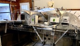
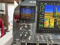
I am having a go at planning out my potential panel (mostly at this stage to make sure i can fit all the switches i need etc).

I had planned for all my engine (SDS) switches on the left hand panel, below the G5 - but it is very tight!

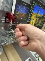
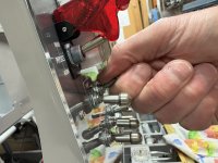
Any opinions or real world experience on the minimum distance below the G5 which switches are usable? I don't have the G5 at this stage to do a mock-up.

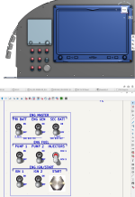
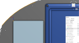
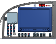
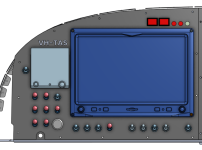
Below are some images from my first go at working with OnShape. If anyone wants to view the actual 3D file, i think you should be able to access it here.

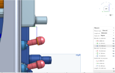
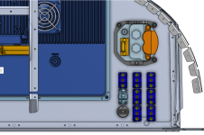
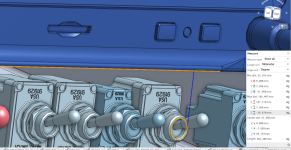
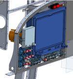
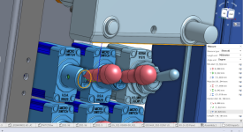
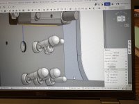
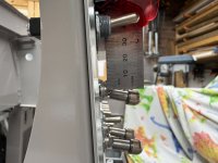
The PFD is as far to the right as it can go. The G5 is as high as it can go (approx 12-13mm inside of the panel edges). The switches are as close to the bottom lower frame as i can get (assiming i move the heater control somewhere else). This leaves the switches around 14mm below (1/2" ish) and 5mm further out than the G5.

These switches would be the engine and generator masters at the top - so only used once per flight.
 

Attachments

  • Screenshot (171).png
    Screenshot (171).png
    217.9 KB · Views: 117
  • Screenshot (172).png
    Screenshot (172).png
    551.8 KB · Views: 124
  • Screenshot (173).png
    Screenshot (173).png
    419.1 KB · Views: 113
  • Screenshot (174).png
    Screenshot (174).png
    167.4 KB · Views: 124
My switches aren't quite that close to the G5, but I don't think you'd have a usability problem.

I'm not sure on a -14, but on a -9 tip up that G5 placement is going to be very close to the canopy frame when it comes down, mostly because the weldment from the factory is not a great fit and cuts the corner (leaving a gap many have filled in various ways). Because of a very delayed finish kit, my panel was done and installed by the time I started on the canopy, and I discovered that the frame would hit the top left corner of the G5. I ended up fixing by cutting and rewelding the canopy frame to be a better fit and eliminate the gap, which also provided the clearance I needed for the G5, but it's something to double check before committing to that placement.
Thanks for the feedback.

I should have thought to check my photos earlier - the -14 is a built up canopy. You can see how the frame of the canopy comes down aft of the panel below (I.e. on the pilots side of the panel surface). The overlap looks to be about the same distance as the canopy structure itself.
 

Attachments

  • IMG_7025.jpeg
    IMG_7025.jpeg
    3.5 MB · Views: 68
I don’t have a 14 but I did use Solidworks to do my 10. I did my 7 manually.
There’s no substitute for making the real thing and sitting there in person putting your fingers on things to answer these sorts of questions. How fat are your fingers? :-)
The other benefit is that you can always eke some more room out of things when you can see how everything interacts.

What you are trying to do is go from prototype to production in one go.
In the real world you design it as you have done, then cut metal and see how it performs. Then iterate as appropriate.

I enjoyed doing it all in a virtual world but to be brutally honest I would have gotten the same result and likely saved 100h just doing it the same way I did the first plane.

Obviously if anyone wants my exact RV10 panel then they could save some work I guess, but for one offs it’s more for education and recreation value rather than efficiency imho.
My plan is to work out the broader picture using this method and once I’m generally happy do a mock up with some acrylic and the g3x sticker pack.

I’m not totally sure I want the PFD all the way over to the right etc. the g5 might need to go somewhere else. It always seems a bit clunky in the centre stack.
 
I don't remember the exact measurement, and I'm not at the hangar to check, but on my RV7 I did basically what you're describing. The G5 was just about as high as I could reasonably get it. At least on the 7 if you tuck it up too high it can make it hard to see because of the glare shield overhang, depending on youre seating position.

My Alt static air switch is above it, The magneto and IBBS switches are right below it, then the start button and batt/alt switch below that. It all worked out fine, and as you say, you only use those switches once per flight.
 

Attachments

  • IMG_8427.jpeg
    IMG_8427.jpeg
    2.6 MB · Views: 56
If anyone out there can give me a measurement which works, that would be awesome. I’m guessing about an inch from the bottom of the g5 bezel to the centre of the switch hole.
 
One thing I didn’t think of in my panel layout was everything laid out fine in flat 2D world, but once installed and considering the pilots line of sight, much of my labeling was blocked by the “shadow”of the G5 and other boxes. You can see what I mean already in some of the photos above. It’s not bad, I would just try to provide a little more space or avoid lettering too close to a box which projects out from the panel. Next time.

Or you can flush mount your G5.
 
I agree, is that laser or silkscreen?
The vast majority of the panel is laser, (there is some simple black over clear stick on, parking brake and anti-skid valve) and the stick grips are rub on.
 
I see what you’re doing and thought I’d throw a different idea at you. I own 2 aircraft and my daily driver has most of the switches mounted in a horizontal bar running across under the panel.

When I removed the panel from my -7, I had to disconnect (PITA) everything to get the panel out.

My new panel is being cut now and we adopted the same idea for the new panel for my -7. All the engine controls, switches and circuit breakers are mounted on a full width bracket under the panel.

Plenty of space for everything to be laid out by groups and if maintenance is required the access is way easier.
 
To be positive you could mock up a panel section to verify the spacing when you have the G5 and switches in hand. Use something easy to work with like .032 aluminum or 1/16” acrylic.

Don Broussard
RV9 Rebuild in Progress- painting
57 Pacer
 

Attachments

  • IMG_5466.jpeg
    IMG_5466.jpeg
    357.4 KB · Views: 35
To be positive you could mock up a panel section to verify the spacing when you have the G5 and switches in hand. Use something easy to work with like .032 aluminum or 1/16” acrylic.

Don Broussard
RV9 Rebuild in Progress- painting
57 Pacer
I will do this for sure. I’ll probably 3d print or cut out of foam some blocks to represent the instruments I don’t have.
 
I see what you’re doing and thought I’d throw a different idea at you. I own 2 aircraft and my daily driver has most of the switches mounted in a horizontal bar running across under the panel.

When I removed the panel from my -7, I had to disconnect (PITA) everything to get the panel out.
Good idea.

On the -14 there is such good access behind the panel - I honestly can’t see why I would need to remove the actual panel tbh. If you take out the screen you have even better access. I’m using the Honeywell NT switches which have screw on lugs. So having to disconnect all the switches would be a massive pain!
 
For some airplanes and some panels, the flush mount bracket that Garmin makes for the G5 might be a solution to having room for switches, allowing the instrument to fit level with the panel. Spruce carries them.

IMG_2729.jpeg
 
Last edited:
A question in regards to switches - do you have a means to turn off the ECU’s or are you doing that with the ignition switches? I’m just curious as I used a three position Honeywell locking toggle - OFF-ECU-IGN. For me, I can do the “mag check” without depowering the ECU.
 
A question in regards to switches - do you have a means to turn off the ECU’s or are you doing that with the ignition switches? I’m just curious as I used a three position Honeywell locking toggle - OFF-ECU-IGN. For me, I can do the “mag check” without depowering the ECU.
No, I was planning for the ecu’s to come on whenever the engine bus is powered. Any power source to that bus and both are on. I’ll have ignition switches to do a ‘mag test’.

I’m going to put my fuel pump and injector select switch on the top. A fuel pump will remain on at all times. Even after shut down. I read somewhere it’s good to power up the ecu’s with a fuel pump running (but don’t know where I read that).
 
Thanks for all the replies.

I have re-done it with the switches 20mm below the G5, and 26mm below the GDU. I was able to shift the G5 inboard a bit (it's about 2mm clearance from the GDU), and this gave me *just* enough room to fit the switches above the heater control circle of the frame. The engine switches straddle the heater control evenly, so switch action won't be impeded by the heater knob (the lower two switches are ignition). The remaining switches under the GDU are battery masters / alternator / x-tie (left group), lights (centre group) and Pitot heat on the right. The ESP inhibit switch fits next to the G5.
 

Attachments

  • Screenshot (179).png
    Screenshot (179).png
    303.9 KB · Views: 32
  • Screenshot (182).png
    Screenshot (182).png
    856.3 KB · Views: 31
  • Screenshot (180).png
    Screenshot (180).png
    247.1 KB · Views: 29
  • Screenshot (177).png
    Screenshot (177).png
    525 KB · Views: 29
  • Screenshot (181).png
    Screenshot (181).png
    884.3 KB · Views: 35
No, I was planning for the ecu’s to come on whenever the engine bus is powered. Any power source to that bus and both are on. I’ll have ignition switches to do a ‘mag test’.

I’m going to put my fuel pump and injector select switch on the top. A fuel pump will remain on at all times. Even after shut down. I read somewhere it’s good to power up the ecu’s with a fuel pump running (but don’t know where I read that).
With SDS there is a “prime” function that occurs four seconds after ECU boot up. That’s the reason to have a fuel pump on if you want that to work. On my installation, I usually delay turning the fuel pump for more than four seconds on a hot start. I’ve found there is less afterfire by not allowing the prime function to work. I assume the afterfire happens due to the wasted spark coil design.
 
With SDS there is a “prime” function that occurs four seconds after ECU boot up. That’s the reason to have a fuel pump on if you want that to work. On my installation, I usually delay turning the fuel pump for more than four seconds on a hot start. I’ve found there is less afterfire by not allowing the prime function to work. I assume the afterfire happens due to the wasted spark coil design.
That’s the one. I found the paragraph (I think) from the manual. If I am understanding it correctly:

Would it make sense to set your start values at zero above a certain cht?

I.e. if the SDS cht sensor (which is in the primer port) is above x degrees then set the start value to 0. At key on, the system will still operate the prime function but just won’t inject any fuel above x degrees?
 

Attachments

  • IMG_7031.jpeg
    IMG_7031.jpeg
    325.5 KB · Views: 4
 
That’s the one. I found the paragraph (I think) from the manual. If I am understanding it correctly:

Would it make sense to set your start values at zero above a certain cht?

I.e. if the SDS cht sensor (which is in the primer port) is above x degrees then set the start value to 0. At key on, the system will still operate the prime function but just won’t inject any fuel above x degrees?
The start values will be set to zero above a certain temp. I am going to suggest to Barry that maybe he add a feature to inhibit the prime function above a user selectable temperature.

My original post was really about having direct control over the ECU's. As the 4 cylinder systems control the injectors differently than the 6 cylinder (all injectors are on the selected ECU vs being split on the 6 cylinder versions), maybe there is no valid reason to have an ECU switch. I was more comfortable having direct control in the unlikely event of a flaky ECU.
On the 4 cylinder, if I understand it right, ecu #1 runs all the injectors. So I just have a switch to move that control to ecu 2 (using the relay boxes) if ecu 1 fails or has issues.

I guess the only issue which could arise was some kind of rough running or detonation caused by one ecu going bonkers and sparking its set of plugs at the wrong time? I’m not sure how you would diagnose that to turn off the correct ECU anyway! That would be the only scenario where I might want an ecu switch, maybe?

Regarding the start prime values - it mentions “key on”. Wouldn’t this mean when you power up the ecu, after 4 seconds, if the engine was warm the duty cycle would be zero and no fuel would go in? (Just trying to understand your procedure for leaving a pump off when the engine is hot). Assuming you have a 0 on the table above x cht.
I know this is big time thread drift, but it’s your thread so here goes.

If I explain this wrong, I hope Ross or someone with more SDS experience will set me straight. I understand the prime function and start cycle enrichment to be two separate functions. The prime function happens on ECU power up after four seconds regardless of the engine temperature (acts like a primer). You can hear the injectors pulse when this occurs. The start cycle enrichment is programmable and has a table for how much enrichment occurs at a specified temperature plus there is a value you can change for how many cycles this occurs. The engine has to be rotating for this to occur, unlike the prime function. There is also another table for enrichment (engine temperature) that acts like a choke and is also programmable.
 
The prime function happens on ECU power up after four seconds regardless of the engine temperature (acts like a primer). You can hear the injectors pulse when this occurs.
Thanks. This is what the manual says about it - since it was under the start enrichment section I assumed it would use the lookup table, but not by the sounds of your description.

“Systems will do 1 injection of fuel at key-on, when the Start value is greater than 0 at any temperature.”
 
I guess the only issue which could arise was some kind of rough running or detonation caused by one ecu going bonkers and sparking its set of plugs at the wrong time? I’m not sure how you would diagnose that to turn off the correct ECU anyway! That would be the only scenario where I might want an ecu switch, maybe?
There is another reason to switch to ECU2 is if you have a MAP sensor fail. (I know the other EFI system much better so not 100% sure this is accurate but believe so since each ECU has its own MAP sensor) A MAP sensor that goes bad will not be a good day if left unswitched.
 
There is another reason to switch to ECU2 is if you have a MAP sensor fail. (I know the other EFI system much better so not 100% sure this is accurate but believe so since each ECU has its own MAP sensor) A MAP sensor that goes bad will not be a good day if left unswitched.
How would this manifest? As I understand the SDS map (limited knowledge!) there are values at the far extremes of the MAP table which mean the engine keeps running if a map sensor fails? (It goes full rich basically for a very low MAP).
IMG_7034.jpeg

Out of interest, here is the START fuel map from the manual - apart from when really hot (assuming this is for a temp sensor failure), the start fuel is zero. The prime function must be seperate to the start fuel MAP.

IMG_7035.png
 
Last edited:
How would this manifest? As I understand the SDS map (limited knowledge!) there are values at the far extremes of the MAP table which mean the engine keeps running if a map sensor fails? (It goes full rich basically for a very low MAP).
View attachment 92009

Out of interest, here is the START fuel map from the manual - apart from when really hot (assuming this is for a temp sensor failure), the start fuel is zero. The prime function must be seperate to the start fuel MAP.

View attachment 92010
Fails, yes but I had a MAP sensor go from ~ 30 inches to 20 inches on take-off twice. My engine went to an ultra-lean mode (Since the system thought it only needed enough fuel to use at 20 inches MP) I had to dial in ALOT more fuel as I crossed the end of the runway and come back around with alarms screaming at me (High EGT's) and land. (This was on my first flight) On the ground did a run-up and everything appeared normal. Even did another full power run-up and everything looked fine. Tried once more and same result but this time I was more ready for it. Went back and started troubleshooting and after reviewing the SD card saw the issue. Replaced MAP sensor and it's been flawless. I wrote a PIREP on this on VAF a few months ago. Not sure if SDS has an automatic way to counter this. I do believe that they use both ECU's and each one in the "normal" switch mode controls 3 injectors so one needs to switch to primary and if it gets worse switch to the back-up position, I believe. Again, I do not use SDS but brand B. I do believe both systems are excellent and the future of GA. I do now try to include the engine monitor display in my scan as this would have shown me the issue but when one gets busy flying the airplane is priority one.
 
Last edited:
Interesting thanks.

I’ve had the misfortune to fly a da40 a few times. It was drilled into us that for *anything* at all, switch ecu’s first thing!!

I reckon for the SDS install, initial actions for any engine issue would be:
- ecu select switch - backup
- fuel boost pump on (this turns on both fuel pumps in my install)
- mixture knob fill right (rich)
- change tanks.

I have been trying to keep procedures as close to a ‘normal aeroplane’ as I can.

Thread drift I know - but so be it! i appreciate the help.
And it depends. I have been helping a 6-cylinder SDS user complete his build. Please SDS users who have more practical knowledge than me chime in. SDS uses both ECU's to power their injectors for 6-cylinder operations. If one switches ECU to back-up instead of having 3 non-functional cylinders running, you might have 6. :eek: 
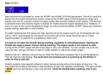
You then need to switch to primary to have 6 cylinders properly running. :giggle: For a 4-cylinder operation as the OP describes a different scenario.
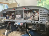
This is meant as educational for all. Be prepared to troubleshoot a MAP failure on take-off regardless if SDS or EFII. Have a plan and procedure and document in your operating manual.

Screenshot 2025-07-08 213417.png
 
Very minor point of clarification. With SDS (and I expect FlyEFII as well), the ECU actually provides the ground trigger for the injectors. The injectors have DC power full time. The modified relay box setup for the 6 cylinder dual ECU models (and now also available for the 4 cylinder dual ECU models) allow for redundant power switching as well without the need for diodes or a dedicated engine bus. This permits true dual bus power separation for all SDS components (ECUs, fuel pumps, coil packs and injectors). A very good addition to SDS that I don’t believe is available with the competition.
 
Update: I went with 24mm in the CAD. (23.992). This translated (amazingly) to 24.5 mm in the real world mockup.

At this distance, the switches are easy to access and the labels can be easily read!
 

Attachments

  • IMG_7975.jpeg
    IMG_7975.jpeg
    3.3 MB · Views: 80
  • IMG_7974.jpeg
    IMG_7974.jpeg
    1.8 MB · Views: 74
  • IMG_7973.jpeg
    IMG_7973.jpeg
    1.5 MB · Views: 67
  • IMG_7971.jpeg
    IMG_7971.jpeg
    2 MB · Views: 76
  • IMG_7972.jpeg
    IMG_7972.jpeg
    2.8 MB · Views: 80
The mockup has been invaluable.

I’ve realised that the stacked locking toggles don’t give enough room to fit your thumb in when the top row is off and the bottom row is on. These are quite far apart too - 35mm centres.

I’ll see if I can move some switches around a bit.

Normal toggles below locking at this distance are fine!
 

Attachments

  • IMG_7983.jpeg
    IMG_7983.jpeg
    2.1 MB · Views: 25
  • IMG_7984.jpeg
    IMG_7984.jpeg
    2.2 MB · Views: 25
Last edited:
What/how did you do the panel labeling? It’s beautiful!
This is just a test. The panel cutout was exported from onshape and brought into Inkscape. This is just a print on cardboard for testing.

Going to see the sign guy on Monday - will have a few options:
- anodized aluminium panel, laser cut to shape then labels laser etched.
- laser cut panel then uv printed in any color / graphics I want.
- laser cut painted aluminium panel, laser etched labels.

He’s got lots of ideas for me but hasn’t mentioned cost yet! Will see on Monday.
Please let us know which method you choose. Thanks!
 
Back
Top