I'm trying to sort out the firewall forward of my RV-4, with a Lycoming IO-320 D1A, with Superior horizontal draft cold air sump and Bendix RSA5 AD1 fuel injection system. three steps forward, 2 back it seems.
Current problem is that it appears very difficult, if not impossible, to fulfill all the requirements that are stipulated for the location of the Red Cube. However, it would seems - from reading as many threads as I can bear on a Sunday morning - that the best location for a fuel injected engine, is after the servo and before the flow divider. Is that a commonly held view that most of us could ascribe to?
Am i right in thinking that a pretty standard routing for the fuel line from servo to divider runs from the servo (remember its at the front, not underneath) under number 2 cylinder, then vertically up through the intercylinder baffle between cylinders 2 and 4, and then terminates with a 90 degree connection to the flow divider?
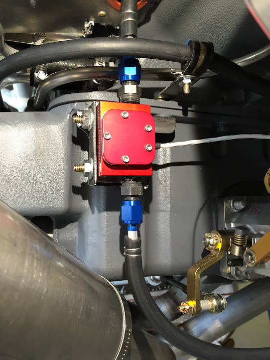
Sooo - can anyone see a problem with mounting the cube directly onto the little elbow that comes out of the top of the servo? I can fabricate a little bracket to help support the cube from the front of the sump/engine case joint.
The only remaining problem as far as I can see is how I actually attach the cube to the servo outlet. The latter is an AN4 male connector; the inlet on the cube is an female 3/8" pipe thread. I cannot see an AN fitting that will give me this combination of connections, so I would need to use a short length of pipe and an adapter in the cube. Any better suggestions?
I could put the cube up at the flow divider end, but I am still left with the 3/8 female pipe thread to a male AN4 flare problem.
As ever, thanks for help!
Chris
Current problem is that it appears very difficult, if not impossible, to fulfill all the requirements that are stipulated for the location of the Red Cube. However, it would seems - from reading as many threads as I can bear on a Sunday morning - that the best location for a fuel injected engine, is after the servo and before the flow divider. Is that a commonly held view that most of us could ascribe to?
Am i right in thinking that a pretty standard routing for the fuel line from servo to divider runs from the servo (remember its at the front, not underneath) under number 2 cylinder, then vertically up through the intercylinder baffle between cylinders 2 and 4, and then terminates with a 90 degree connection to the flow divider?
Sooo - can anyone see a problem with mounting the cube directly onto the little elbow that comes out of the top of the servo? I can fabricate a little bracket to help support the cube from the front of the sump/engine case joint.
The only remaining problem as far as I can see is how I actually attach the cube to the servo outlet. The latter is an AN4 male connector; the inlet on the cube is an female 3/8" pipe thread. I cannot see an AN fitting that will give me this combination of connections, so I would need to use a short length of pipe and an adapter in the cube. Any better suggestions?
I could put the cube up at the flow divider end, but I am still left with the 3/8 female pipe thread to a male AN4 flare problem.
As ever, thanks for help!
Chris
Last edited: