So you're dismissing this data set as mere luck.
Although there is undoubtedly
some variation in flow capacity between randomly selected heads of
any brand, it is probably not so large as we're being led to believe.
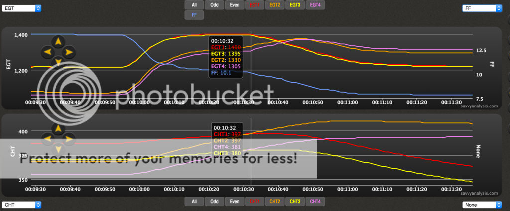
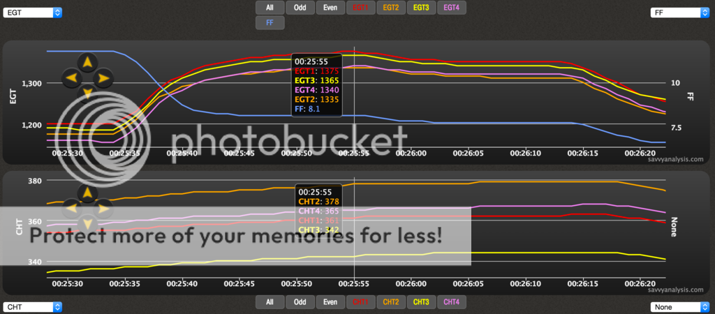
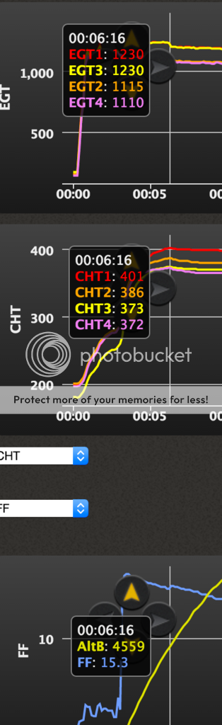
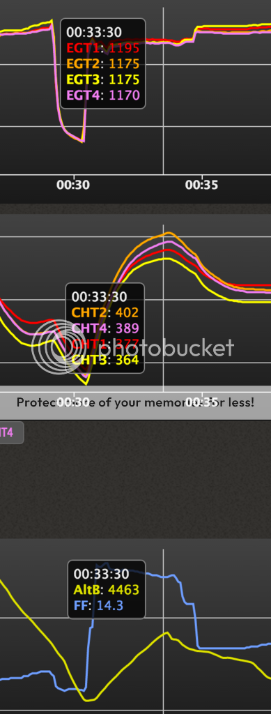
Maybe Don's customer just got lucky, but gee whiz, GAMI spreads of 1 GPH or less are pretty standard right out of the box with constant flow injection. My own was less than 0.4, and only required one restrictor 0.005" larger and one 0.005" smaller to balance.
May I suggest an entirely different explanation?
As demonstrated, wet flows and dry flows are not at all the same. Until fully in vapor phase, fuel tends to follow its own path when airflow changes direction.
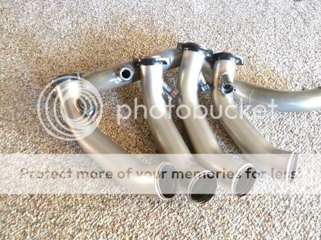
As currently configured, the EFii injectors are located on the intake runners, pointed downward, perpendicular to the crankshaft centerline. However, the individual intake runners intersect the injector spray pattern at either four or six different angles in two different planes (approach angle and runner bend), at the curve in the runner. The result is entirely non-symmetrical; no intersection of fuel spray and airflow is the same.


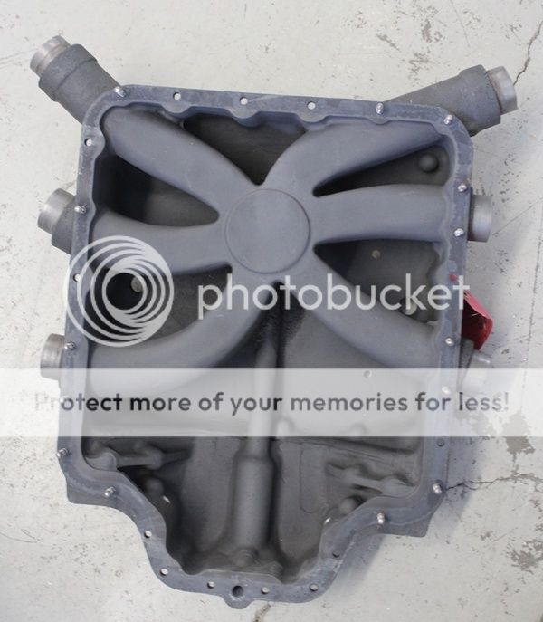
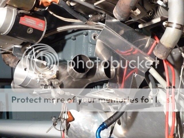
Although much is made of an electronic injector's "highly atomized fuel spray", it is useless if a high percentage of those tiny fuel droplets fail to reach vapor phase, or clump back together into larger droplets, or simply wet the walls of a relatively cool manifold runner. Those are classic problems in the wet flow from a carb or single point injection, and I suggest that the EFii injector placement (below, A) is subject to the same.
The vast majority of port fuel injection designs (mechanical or electronic) place the injector so that it sprays fuel at the back side of the hot intake valve (C). The combined heat and pressure drop at valve opening instantly flashes the fuel to vapor, even if pooled there.
Re-positioning the electronic injector, either to an optimum position on top of the head (C, the standard Lycoming injection port), or to a less optimum but still better position pointed up into the intake port (B) might prove to be a worthwhile experiment.
Of course, position (B) would tend to trap vapor bubbles following a hot shutdown, and thus may negate a key benefit, simplified hot starting as compared to constant flow injection.
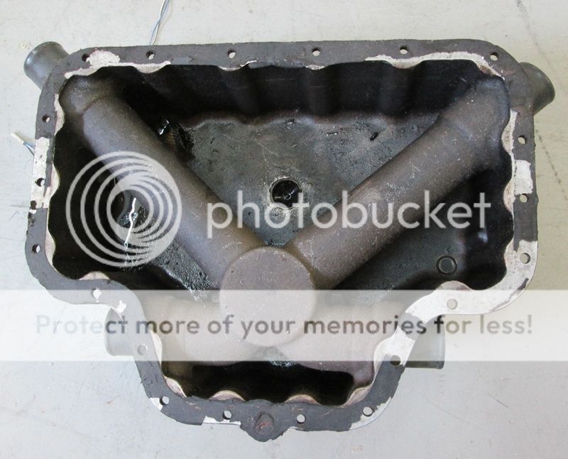
Further to injector placement, anyone who has ever played around inside a flowing intake port with a manometer probe knows that there are significant pressure variations at various points, notably around curves. Here, fuel delivery is dependent on deltaP between the fuel rail pressure and the manifold pressure
in the immediate vicinity of the injector. The fuel pressure regulator varies rail pressure to maintain deltaP, but necessarily assumes that manifold pressure is the same in all runners. Variations in local manifold pressure would result in variations in fuel delivery at individual injectors.


")