Van's Air Force

The definitive Van's Aircraft support community! Buying, building or flying an RV? Join our exclusive family of mentors and enthusiasts!

How to set up cooling for internally regulated alternator? Anyone have reliability issues due to heat?

nickw9815

Well Known Member
Hello,

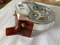
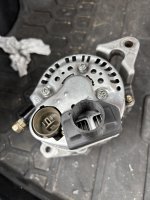
I have an RV6a that’s had a plane powered alternator fail at 600 hours. PP thinks this could be heat related. How do other people have their alternators?

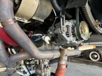
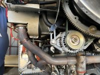
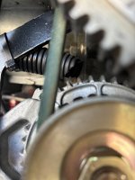
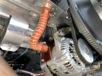
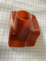
1. My alternator has a ram air pressure tube aimed at the front from the builder. The alternator guide suggests aiming this at the back. We plan to replace the tube and aim it towards the rear.
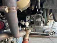
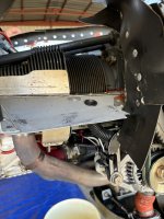
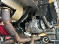
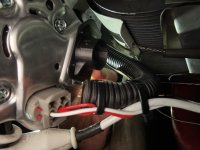
2. The alternator is ~6” from the exhaust. I’ve had a few mechanics suggest adding a heat shield here. Any thoughts on doing this?

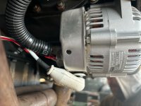
As a general question, have other people had alternator reliability issues with an internal regulator? Vans said that internally regulator alternators are the norm, but Plane Power said that external regulators are much more reliable due to better cooling.
 

Attachments

  • IMG_6255.jpeg
    IMG_6255.jpeg
    3.9 MB · Views: 337
  • IMG_6256.jpeg
    IMG_6256.jpeg
    3.6 MB · Views: 323
  • IMG_6257.jpeg
    IMG_6257.jpeg
    4 MB · Views: 282
  • IMG_6260.jpeg
    IMG_6260.jpeg
    2.3 MB · Views: 264
  • IMG_6261.jpeg
    IMG_6261.jpeg
    2 MB · Views: 341
Alternator cooling flow is IN at the ends, OUT at the periphery. The above is bass ackwards.
Does anyone make or have a photo of a plenum to direct air to the rear of a PP alternator? I am trying to install something, but don’t want to reinvent a wheel. Thanks in advance.
 
I had alternator reliability issues with an internally regulated PP that began failing regularly when hot. My plane now has an externally regulated B&C alternator.

With a new internal regulator fitted my old alternator lives on in another aircraft with more than 1000hrs on it. When it begins failing again I think it’ll be time for its new owner to replace the regulator once more - or change to externally regulated.
 
Here’s my install on a B&C 60 amp. Works fine after 1200 hours.

View attachment 75325
That’s close but the tube should direct the air in the slots on the back side of the alt where the diodes are.
I ran the tube down the back, cut a 2” slot in it which faces the alt and plugged the end of the tube so all the air is directed at the rear.
Ran my last b&c to TBO and installed a new one on the new engine even though there was nothing wrong with the old one.
Regulator failure is almost always heat related.
 
Last edited:
I have a PP internally regulated 60 A that had regulator failure prematurely. I put a shield on the nearby exhaust pipe and directed one tube at the aft end of the alternator. No problems in 600 hrs since.
 
Check the cooling fan mounted behind the pulley. Some alternators have fans to suck cooling air in from the back, some others blow air front to back. Once you determine which you have… easy to figure out where to direct ram air to front or back.
 
I have 2 thermocouples I can place almost anywhere FWF. Sure, blast tubes help but temps this far forward only run 25 - 35 degrees over ambient front of alternator to rear on the ground and 10 to 20 degrees in cruise. Not that hot.
 
Based on the proximity to the exhaust, I think a simple heat shield is good insurance. That pipe is glowing orange most of the time you are flying, so anything to cut down on the radiant heat being thrown at the diodes is worth doing.
 
Here’s my install on a B&C 60 amp. Works fine after 1200 hours.

View attachment 75325

The illustrated blast tube is supplying cold air at the diode cooling outlet. Some cool air may be finding it's way to the regulator, and it may even be doing some case cooling, but it's not efficient.

Vern's blast tube is roughly in the same location, but it's directed into the rear cover space.

This is the rear fan on a Plane Power (Bill Lane photo). Installed rotation is clockwise.

Rotation Direction Brush End PP.jpg
 
Last edited:
I have a blast tube, plus a thermocouple to measure alternator case temperature. Recent flights give me a 100F +/- case temperature typical (around 40C). Checking the data logs, I see it is negatively correlated with airspeed, so the blast tube is doing it's job.


Excellent, as usual. Could you slap a little strip of duct tape across the blast tube inlet and get temperature with no flow?
 
I have the 40a BnC alternator, and the install instructions say a blast tube is not necessary - however, after reading this post I think I’ll install one and have it aimed the way Vern did. Free, and possible good long term result.
 
Heat shield, and scat tube mounted to the inlet ramp with a small “scoop” about the size of one’s thumb facing forward. I believe this increases the airflow through the scat tube, but have no data to prove it. Directed at the regulator as above.
If you want to do some forensic analysis on your failure, it’s pretty easy to access the regulator. The typical heat failure will show in the potting as an obvious swelling or bump.
 
I have a PP internally regulated 60 A that had regulator failure prematurely. I put a shield on the nearby exhaust pipe and directed one tube at the aft end of the alternator. No problems in 600 hrs since.
Any chance you can share photos of your set up?
 
Heat shield, and scat tube mounted to the inlet ramp with a small “scoop” about the size of one’s thumb facing forward. I believe this increases the airflow through the scat tube, but have no data to prove it. Directed at the regulator as above.
If you want to do some forensic analysis on your failure, it’s pretty easy to access the regulator. The typical heat failure will show in the potting as an obvious swelling or bump.
Do you have photos of the set up you are referring too? Thanks.
 
Do you have photos of the set up you are referring too? Thanks.
Out of town but will try to get a photo of the inlet. Everything else is what others posted here. Heat shield between the alternator and cross over, standard Vans stainless shield.
 
It should be fairly easy to weld a tube nipple onto the rear diode shroud of the alternator as a dedicated anchor point/inlet for a length of blast tube. I may have done this on one of my earlier airplanes or thought about it often enough that I “think” I actually did it. Getting old is a bitch.

Anyway, I still stand behind it as a “good idea”.
That happens to me way too often.....
And I will order an item that I think I need, only to find out I already have one on the shelf when I go to place the new one next to it.
 
Great thread. I had a blast tube aimed right at the side of my ND and thought I was set up good until I saw Dan’s remarks. Went back to the drawing board and came up with this..
I hope now I’m set, again..

IMG_0986.jpegIMG_0992.jpeg
 
Promised picture of blast tube inlet.
I chose to cold form a small scoop out of concern that the air moving across the tube may have a siphon effect. However, I have no proof, or understanding of how the air moves across the ramp to know if it is necessary, helpful, or a waste of time.IMG_9632.jpeg
 
I installed a new alternator and updated my cooling. I also plan to install a heat shield. Any feedback?
 

Attachments

  • IMG_6591.jpg
    IMG_6591.jpg
    2 MB · Views: 111
  • IMG_6590.jpg
    IMG_6590.jpg
    1.8 MB · Views: 113
Don’t try this at home kids but Steve Cogswell at Corona came up with this in fiberglass for his magnificent RV8.
 

Attachments

  • IMG_0685.jpeg
    IMG_0685.jpeg
    1.5 MB · Views: 191
  • IMG_0689.jpeg
    IMG_0689.jpeg
    2.6 MB · Views: 189
  • IMG_0683.jpeg
    IMG_0683.jpeg
    1.1 MB · Views: 189
Smoke Test --

I spun up the alternator using a drill with a polishing pad arbor. You can see where you should position the blast tube...or make a shroud....

(smoke courtesy of Palo Santo)

View attachment 76614
What direction is the fan actually blowing? The standard “fan” on the stupid simple auto parts alternators may be spinning backwards, blowing air forward, sucking air into the regulator.
My understanding is Plane Powers version was “modified” so the fan blew back.
I need to look at mine.
Anybody know?

There are two fans, actually. When the alternator is spun the correct direction (CW as viewed from the cockpit / CCW as viewed from the front of the airplane) each fan draws air in from the ends of the alternator housing and into the center of the stator windings and exhausts from the sides of the alternator body.

I have video to prove it 😁
 
@bjdecker I wouldn't mind seeing that video for my own knowledge!

With what you're saying, it sounds like directing cooling on those heat fins would be the most effective way to cool the alternator.
 
Excellent video and test.
Just keep in mind, folks may have a different alternator. It may only have one fan. In addition, if that alternator was for an application that mounted on the opposite side of the engine, or backward mounted, the fan may spin on the wrong direction.
This was a discussion from a long time ago….so working off of memory here.
 
I've been informed by someone who actually tested it, that the black corrugated tubing restricts airflow terribly. I used it (5/8 ID, 3/4 OD) to cool my alternator and measured temps as high as 180F. Use smooth inside wall tubing (scat)!
Not doing so is probably what will cost me 100's of repair hours and thousands of $ in replacement parts (incl propeller). Well, that and piloting skills. More about that later when NTSB is done and I have bench tested alternator and done battery autopsy.
Oh, and those of you that have battery forward of firewall, do put a temp probe on it and check temps against battery manufacturer's specs, especially if you have only electronic FI and/or ignition (no mags).
 

Attachments

  • P1030031.JPG
    P1030031.JPG
    69 KB · Views: 67
Last edited:
In alternator convention, shaft rotation is as viewed from looking at the pulley. So in a Lyc application, the shaft is rotating CCW. Most automotive applications spin the alternator CW, and have the fan blades angled appropriately (2 fans in the old Denso designs we typically use).

Pre-2000 or so FWD Honda 4-cylinders spin "backwards" (accessories on LH side of car) and therefore have CCW fans. These are the fans which PlanePower and B&C use (both of these guys use aftermarket versions of (Nippon) Denso designs).

That is the answer to the question, as I remember it. So, if you’re not using a Plane Power or alternator intended for our application, we may be spinning backward, which isn’t a problem for power generation, but the fan will not cool as well.
By the way, I just checked my ‘85 GMC with the LT350 and alternator spins CCW, mounted on right side. It has one external fan, oriented correctly, and It is a Nippo-Denso.
 
By the way, I just checked my ‘85 GMC with the LT350 and alternator spins CCW, mounted on right side. It has one external fan, oriented correctly, and It is a Nippo-Denso.
No. Facing the pulley, the Chevy spins CW, which is the opposite of Lycomings.

To see this better on the truck, have someone bump the starter so that you can see the beginning of rotation before the engine starts.
 
No. Facing the pulley, the Chevy spins CW, which is the opposite of Lycomings.

To see this better on the truck, have someone bump the starter so that you can see the beginning of rotation before the engine starts.
I believe you!
 
I’m currently machining a little adapter to direct all the flow on the heat sink. Photo of the prototype attached.
 

Attachments

  • IMG_6702.jpeg
    IMG_6702.jpeg
    1.9 MB · Views: 87
  • IMG_6763.jpeg
    IMG_6763.jpeg
    2 MB · Views: 88
For everyone’s awareness, there is a new thread where we are discussing ways to design better cooling:

 
Back
Top