Van's Air Force

The definitive Van's Aircraft support community! Buying, building or flying an RV? Join our exclusive family of mentors and enthusiasts!

Cooling solution for Plane Power Alternator

bjdecker

Well Known Member
Ambassador
A recent thread on this got my creative juices flowing. The only thing better than being proficient with Fusion360 and having a kick-butt 3D printer, is having a friend with Jedi-like CAD skills and a 3D printer :)

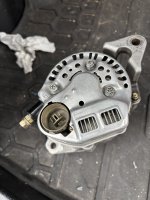
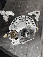
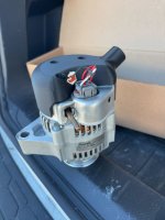
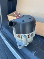
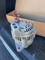
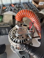
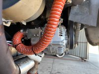
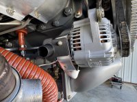
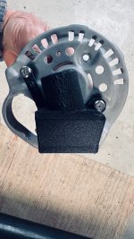
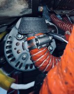
Using a spare H.E.T. (nee Plane Power) Internally Regulated 60A alternator (Model 99-1012, aka AL12-EI60), we modeled up a 1" duct/diffuser that would attach to the back of the alternator and use one of the existing screws to hold it in place. On the side, I'm either going to use a couple of AN507-6R6 screws to anchor the drape, or use VHB tape...we'll see.

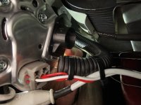
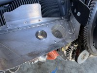
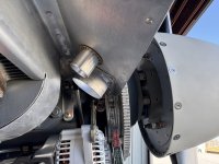
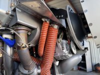
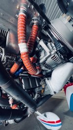
The 1" duct would attach to an aluminum flange located on the right front baffle floor/ramp adjacent to the heater air inlet (typ. RV-7).

Pictures attached:

IMG_6869.jpeg
IMG_6870.jpeg

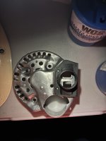
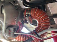
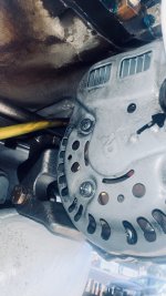
Additionally, I plan on modifying the rear cover of the alternator to open up the "holes" over the heat sink fins.
 
I had the same idea and made this. Plan to attach it to the alternator with safety wire. I am making a machined one (AL 7075-T6) now for ~$70. I decided not to put a 90° bend in it like yours due to extra complexity
 

Attachments

  • IMG_6762.jpeg
    IMG_6762.jpeg
    2.3 MB · Views: 292
  • IMG_6763.jpeg
    IMG_6763.jpeg
    2 MB · Views: 290
  • IMG_6702.jpeg
    IMG_6702.jpeg
    1.9 MB · Views: 286
Last edited:
Does the stock shroud just unscrew in order to fit the adapter?

Yeah the back part can unscrew. Plan is to use RTV to seal the adapter to it, and to drill some holes and safety wire the adapter to the back part.

I’ll post an update once I have the machined version installed. I’m also planning on using thermocouples to see if there is a noticeable temperature difference.
 

Attachments

  • IMG_6704.jpeg
    IMG_6704.jpeg
    1.4 MB · Views: 93
As I've been preaching here for years, you can definitely use 3-d printing for "underhood" applications, as long as you use the SLS process with nylon (as Windform above), or MJF process with nylon. Parts from consumer-grade machines typically aren't robust enough for this application, but there are SO many vendors out there nowadays to make parts for you. Just upload your files and a week later have parts. Could also 3-d print in metal, but that's overkill unless you want to bolt the part to the exhaust system...

This oil cooler duct has been on my -6 for around 5 years and no distortion or loss of bolt preload: https://vansairforce.net/threads/ducts-matter.188113/.
Your oil cooler design is very cool. Looks like reinforced nylon from MJF.
 
@bjdecker Are you planning to CAD up a full duct cover like the NASCAR one? I’ll do it when I’m back from the holidays and am happy to share CAD.

I do wonder how much of a benefit a full cover will have over a partial cover
 
.....I do wonder how much of a benefit a full cover will have over a partial cover
A full cover would be better to help cool the rectifier diodes instead of just the regulator.

One thing to keep in mind is the rear cover screws on the Denso are structural in that they hold down (and complete the ground circuit) of the rectifier bridge. So if you replace the entire rear cover make sure you incorporate metallic inserts in the holes to support the hex nuts, like Windform did above. Just torquing down on plastic will cause the plastic to deform with time and lose preload. My oil cooler duct works without inserts as the bolt torque is low, bearing surface is large, and does not complete an electrical circuit.

Looking at the photos below, it's probably a better idea to make a shroud which slips over the entire rear cover, leaving the original cover in place. Make the shroud fit around the perimeter with ~1/2" flanges and attach with RTV.

1735174265551.jpeg1735174288055.png1735174416058.jpeg
 
A full cover would be better to help cool the rectifier diodes instead of just the regulator.

Stator too. The Windstream page notes a 20F reduction. And recall the Plane Power rear case cover has shown some issues with rear bearing bore enlargement. The likely scenario is expansion of the bore due to heat, releasing the bearing shell enough for fretting, rotation, and wear. If true, cooing the whole rear cover has to help.

If some of these get made, I'd be pleased to thermocouple an installation.

Break.

Off topic, but does anyone with contacts happen to know the model described on the Windform page as "a standard NASCAR Bosch alternator"? Is there some special alternator?
 
Last edited:
Stator too. The Windstream page notes a 20F reduction. And recall the Plane Power rear case cover has shown some issues with rear bearing bore enlargement. The likely scenario is expansion of the bore due to heat, releasing the bearing shell enough for fretting, rotation, and wear. If true, cooing the whole rear cover has to help.

If some of these get made, I'd be pleased to thermocouple an installation.

Break.

Off topic, but does anyone with contacts happen to know the model described on the Windform page as "a standard NASCAR Bosch alternator"? Is there some special alternator?
Hey Dan, I plan to work on this casually in the new year. I have access FDM Nylon reinforced printers and I’d be happy to send you one if you are interested in testing it with thermocouples. Long term though, we should use a better material or process to handle the high temps and be more fatigue resistant.
 
Hey Dan, I plan to work on this casually in the new year. I have access FDM Nylon reinforced printers and I’d be happy to send you one if you are interested in testing it with thermocouples. Long term though, we should use a better material or process to handle the high temps and be more fatigue resistant.

Have found several PP's with enlarged rear bearing bores, I would be happy to test. Already have thermistors on long leads in the engine compartment.

Note a detail about the Windstream rear covers. There's no gap between the edge of the cover and the case. With no gap, hot air exiting radially can't get recirculated back to the fan entry. The cheap rear cover on the Plane Power is sloppy that way.
 
@nickw9815 -- yes, I am heading to the wrecking yard in the hopes of finding an ND alternator cover that lines up with the PP EI12-AL60. The Bosch AL256X shown is off by 90° or so and has different venting in the aft case -- more actually...but we knew this...

Also, The PP uses M4x.7 - 25mm screws and not studs/nuts, like the Bosch.

In the interim, I am going mount up the part that I have and give it a whirl.
 
I've got about 1500hrs on my PP alternator with no issues, and did something I haven't seen referenced yet. The blast tube is secured such that it points at the voltage regulator section, but the blast tube itself consists of two pieces of conduit grafted together such that the air going to the alternator has to make a sharp turn to get there. The lower part of the conduit is plugged with a disc shaped piece of baffle material sized to fit the ribbing and glued in place with some more RTV. The disc shaped piece of baffle material has a small hole in it. The idea is that any water that enters the inlet of the blast tube accumulates in the lower part of the conduit and drains while the bulk of the air makes the turn and goes to the alternator.

IMG_7656.JPG
 
In
I've got about 1500hrs on my PP alternator with no issues, and did something I haven't seen referenced yet. The blast tube is secured such that it points at the voltage regulator section, but the blast tube itself consists of two pieces of conduit grafted together such that the air going to the alternator has to make a sharp turn to get there. The lower part of the conduit is plugged with a disc shaped piece of baffle material sized to fit the ribbing and glued in place with some more RTV. The disc shaped piece of baffle material has a small hole in it. The idea is that any water that enters the inlet of the blast tube accumulates in the lower part of the conduit and drains while the bulk of the air makes the turn and goes to the alternator.

View attachment 77044

Most of these alternators do last thousands of hours, but some of us do have heat related failures. Either way, better cooling is better.

Your cooling actually seems to be going against the direction of the fan. PP always recommends aiming the tube on the back side

Also, is that a heat shield on your exhaust?
 
@nickw9815 -- yes, I am heading to the wrecking yard in the hopes of finding an ND alternator cover that lines up with the PP EI12-AL60. The Bosch AL256X shown is off by 90° or so and has different venting in the aft case -- more actually...but we knew this...

Also, The PP uses M4x.7 - 25mm screws and not studs/nuts, like the Bosch.

In the interim, I am going mount up the part that I have and give it a whirl.
Nice, let me know how it goes. I think a little adapter to direct all the flow on the heat fins will be much better than the standard way. But the best does seem to be a shroud over the entire back that is air tight so nothing leaks.
 
You are cooling the Voltage Regulator. What about the rectifier, diodes. Those get the hottest.

HEAT shields between the back of the alternator and heat source (exhaust pipes, engine) is a winner. The shield does not have to fit like a glove. You don't want back of alternator with a line of sight view of a hot exhaust pipe.

Inferred heat as well as convective heat can be reduced with shields, bolted to exhaust, or open shield bolted on back shield the alternator.
Air flow is also key, convective cooling. A blast tube on back is a bonus. Where and how do you direct the air? Picture above with corrugated tube directing air under stock shield/cover is simple and helps cool the diodes.
 
Last edited:
Likely not a concern but with a full cover on the back is there any concern of the alternator getting to cool? What if flying at -15C and only getting -15C air?
 
Likely not a concern but with a full cover on the back is there any concern of the alternator getting to cool? What if flying at -15C and only getting -15C air?
Silicon based electronics are usually "ok" down to -40° IIRC
 
Most of these alternators do last thousands of hours, but some of us do have heat related failures. Either way, better cooling is better.

Your cooling actually seems to be going against the direction of the fan. PP always recommends aiming the tube on the back side

Also, is that a heat shield on your exhaust?

The installation documents for my alternator have exactly zero to say about cooling, but mine was from back when Plane Power was it's own standalone company. And after pulling it apart, I'm not convinced the fan actually does anything. Anyway, it's worked well enough and I'm not looking to change something without cause.

No heat shield on my exhaust.
 
REVISION 2 Installed!

I decided to move the air inlet 90° from the original location and point it "forward" by 10°. This allowed for a more elegant routing of the duct. I used an M4x.7x35mm screw for the hold down on the back of the alternator, and a single AN5096R6 to attach the side to the alternator cover.

If interested see https://www.atx3dsolutions.com

See pics.


IMG_6883.jpeg

IMG_6880.jpeg
IMG_6882.jpeg
IMG_6884.jpeg
 
Last edited:
The installation documents for my alternator have exactly zero to say about cooling, but mine was from back when Plane Power was it's own standalone company. And after pulling it apart, I'm not convinced the fan actually does anything. Anyway, it's worked well enough and I'm not looking to change something without cause.

No heat shield on my exhaust.
Excerpt from page #2 of the installation docs circa 2005 attached...

Screenshot 2024-12-28 at 3.58.04 PM.png
 
Excerpt from page #2 of the installation docs circa 2005 attached...

View attachment 77192
Interesting. There is no such note like that on my instructions from 2009. Maybe I have a different model of alternator.

Edit to add: Regardless of alternator model, the main idea from my post still stands - avoid ducting water from the blast tube into the electronics. Electronics and water don't mix well.
 
Last edited:
I never considered water ingestion for the alternator cooling before. If taking it off the rear of the baffles, it's likely not an issue. If you take the air off inlet ramps, probably a huge issue. I'm waiting for my new tubing to arrive and will likely put a definitive low spot or even a full loop in the tube with a 0.25” drain hole before routing the airflow to the alternator.
 
Interesting. There is no such note like that on my instructions from 2009. Maybe I have a different model of alternator.

Edit to add: Regardless of alternator model, the main idea from my post still stands - avoid ducting water from the blast tube into the electronics. Electronics and water don't mix well.
I actually called Hartzel about installing cooling and specifically asked about water coming through the vent tube. The tech rep with whom I spoke said cooling was recommended and he was not concerned about water intrusion. He said the only place he would protect from water was the plug and recommended putting RTV around the plug.
 
The Beech Baron and the Bonanza have the alternator mounted out front, not aware of any water related problems.

f57485_e389482ee9434e19b8e42620177260a9~mv2.jpg
 
Last edited:
Here is my first pass at a duct for the rear of the alternator. Printed with PA12 reinforced with carbon (heat deflection temp of 300F), and has metal compression limiters where the bolts go.

Duct aims right at the heat fins and at a slight angle to get lateral flow across the fins. I applied a consistent amount of airflow via a shop vac to the alternator back plate with and without this duct, and there is significantly more flow through the back plate holes with the duct.

I plan to fly with this once and measure the temperature change on the alternator. If it works well, I'll machine one out of Al.
 

Attachments

  • IMG_7094.jpg
    IMG_7094.jpg
    1.5 MB · Views: 109
  • IMG_7095.jpg
    IMG_7095.jpg
    1.4 MB · Views: 112
  • IMG_7096.jpg
    IMG_7096.jpg
    1.2 MB · Views: 106
So the above shroud I made fits very well to the alternator and increases flow rate. But, it sits very close to the exhaust and cylinders and I need it to be made from a higher temp material.

So my short term solution was to build a bracket to position the scat tubing right on the heat fits.
 

Attachments

  • IMG_7129.jpeg
    IMG_7129.jpeg
    2.5 MB · Views: 136
  • IMG_7132.jpeg
    IMG_7132.jpeg
    2.2 MB · Views: 135
  • IMG_7135.jpeg
    IMG_7135.jpeg
    2.4 MB · Views: 137
So the above shroud I made fits very well to the alternator and increases flow rate. But, it sits very close to the exhaust and cylinders and I need it to be made from a higher temp material.

So my short term solution was to build a bracket to position the scat tubing right on the heat fits.
Nick,

Consider enlarging the two square holes covering the heat sink, make one larger rectangle opening to fully reveal the heat sink.

Do whatever you can to remove the bend in the SCAT/SCEET duct.
 
I have also installed the atx3dsolutions.com adapter. I’m happy with the part. It will be interesting to see how it holds up. ( I also used the blast tube kit from experimentalaero.com and it worked great. )
 

Attachments

  • IMG_3662.jpeg
    IMG_3662.jpeg
    3.1 MB · Views: 162
  • IMG_3663.jpeg
    IMG_3663.jpeg
    2.9 MB · Views: 145
  • IMG_3664.jpeg
    IMG_3664.jpeg
    2.3 MB · Views: 136
  • IMG_3665.jpeg
    IMG_3665.jpeg
    3.7 MB · Views: 133
  • IMG_3666.jpeg
    IMG_3666.jpeg
    4.1 MB · Views: 160
Last edited:
Another comment on a cooling adaptor made by 3D Print Solutions in Austin, TX.

I have an ND 14824/14870 alternator and it mounts rotated a bit differently the the PP units. The cooling fins on mine are on top close to the bottom on the #1 cylinder to the shroud had to be shaped differently than the one the WB-avl , and BJDecker (posts above) used from Dwain that 3D Print Solutions sells.
I talked with Dwain and sent him photo's of what I needed and he made one that fits the ND alternators also.
I enlarged the inlet opening on the alternator back plate to allow more air in. It's angled to nestle in close to the case/cylinder. Fits like a charm on my setup.
I've been running it now for about 20 hours and it's holding up well. Easy installation and 3D Printing Solutions also sells a scoop to install in the inlet for a 1 inch SCAT/SKEET tube for a clean installation.


Very happy with the product and Dwain's working with me to make a product that fit the ND alternator.

You can reach out to 3D Print Solutions at this link.
 

Attachments

  • ND 14870 cooling scoop 2.jpg
    ND 14870 cooling scoop 2.jpg
    564.1 KB · Views: 119
  • ND 14870 cooling scoop 4.jpg
    ND 14870 cooling scoop 4.jpg
    429.9 KB · Views: 118
  • ND 14870 cooling scoop 3.jpg
    ND 14870 cooling scoop 3.jpg
    780.7 KB · Views: 123
  • ND 14870 cooling scoop 6.jpg
    ND 14870 cooling scoop 6.jpg
    400.8 KB · Views: 119
  • ND 14870 cooling scoop 5.jpg
    ND 14870 cooling scoop 5.jpg
    613.5 KB · Views: 117
  • ND 14870 cooling scoop 7.jpg
    ND 14870 cooling scoop 7.jpg
    954.7 KB · Views: 124
Last edited:
Would you be willing to share the 3d model ? I woukd like to print this as well.

Thanks!

Did the 3D model of this cooling manifold ever get shared? I can see where there are some links in this thread to possibly purchase the manifold, but the links are dead. I need to devise a cooling manifold for my alternator as well. If none of these depicted are available then I'll create one and share the file for others.
 
I'd advise significant caution to anyone considering 3d printed parts fwf. There was a fatal crash not long ago that appears to be caused by a 3d printed elbow in the air intake collapsing, causing engine failure.

Now obviously the downstream end of a blast tube to the alternator isn't as critical a part, but I'd suggest trying to keep the hot things and the melty things well separated.
I suspect there’s more to this story…

Got a link to the NTSB docket that you can share?
 
Very few 3d printed materials are rated for the temps our engines get (FDM printing relies on being able to easily melt plastic...). A 3d printed design might work for a few flights, but what if you idle for a long time and get heat soak? I would highly recommend you just pay for someone to machine it out of Al. Or just build a sheet metal one...

You'll notice in my above posts I made a nice 3d printed shroud but ended up just using sheet metal...

Here is a link to an article on the melted 3d printed intake: https://www.bbc.com/news/articles/c1w932vqye0o
1776198538725.png
 
I suspect there’s more to this story…

Got a link to the NTSB docket that you can share?

It was here in the UK I believe.
Will try to find the info, but I seem to remember the guy had bought the part from a vendor at OSH.
 

Thanks for that. Your point is valid; Don't use the wrong material for the intended environments.

50°C is a summer day here in Central Texas ;) NVM the oven that's the underside of the Cozy's cowl...

The item that I showed earlier was printed using CF-PETG (+70°C) and ultimately CF-PAHT (194°C) . The plastics used in the alternator regulator itself will melt before that.
 
This is a great channel... He is a Cozy pilot, owner and although he did not build it he has rebuilt it a few times, and has the new repairman authority on this plane. He did some videos on that process as well. Good pilot as well, very good IFR flight videos. I had my instrument student watch a few, great COM, flight planning, decision making and risk management.

 
I have had a 3d printed cooling shroud for my alternator for the last ~250 hours, printed from Bambu PA6-CF. It’s held up absolutely fine, even on hot summer days in Spain.

Of course if the shroud were to melt, the engine won’t stop, unlike the intake pipe on that Cozy. So I felt it was fine to use.

I designed it in a hurry so there’s definitely no airflow optimisation but I figure it’s blasting air into the alternator so that must be good.

IMG_4552.jpeg
 
I have had a 3d printed cooling shroud for my alternator for the last ~250 hours, printed from Bambu PA6-CF. It’s held up absolutely fine, even on hot summer days in Spain.

That is a nice compact design. You should post the file somewhere.
 
I have had a 3d printed cooling shroud for my alternator for the last ~250 hours, printed from Bambu PA6-CF. It’s held up absolutely fine, even on hot summer days in Spain.

Of course if the shroud were to melt, the engine won’t stop, unlike the intake pipe on that Cozy. So I felt it was fine to use.

I designed it in a hurry so there’s definitely no airflow optimisation but I figure it’s blasting air into the alternator so that must be good.

View attachment 115471
I also appreciate the heat shield on the exhaust. Did you make that or was it purchased? I had one I got from spruce but it broke
 
Back
Top