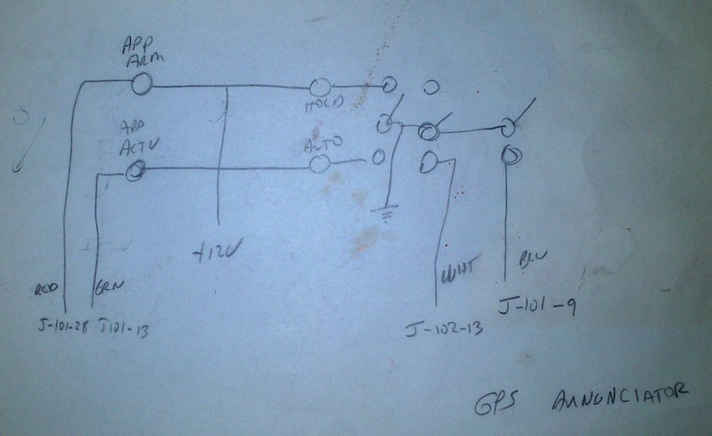
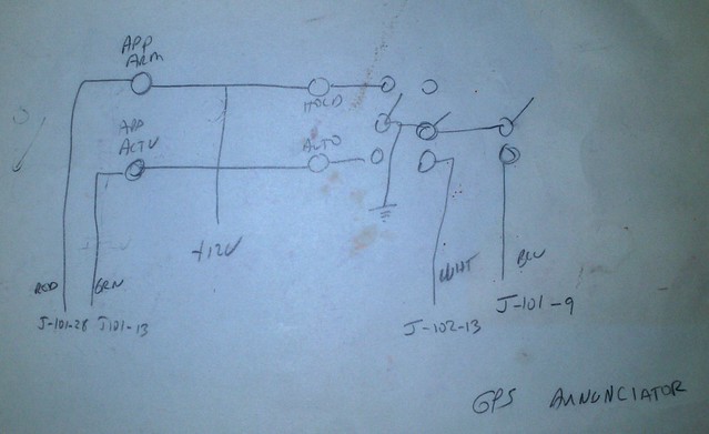
I don't have my schematic available to post at the moment, but can dig it up if you like. My panel isn't for the GPS, but the same circuits should apply. I have 5 light circuits in my annunciator. There are both a dim and test function. The unit is very simple, and for just a couple lights wouldn't even need a board or case.
All of my lights are made to have a common pwr (+) with switched ground (-). The circuit would work for a common ground also, but you would have to reverse the diodes.
The dim switch is SPDT, the com is connected to ships power, one lead goes to the DIM buss and the other to the On Buss.
The ON buss is connected to the lights by diodes to isolate it from the DIM buss.
The DIM buss connects to each light through a resistor.
The Test switch is SPST Mom and connects from ground to the TEST buss.
The TEST buss connect to each light through a diode. That keeps the lights trigger (contact) signal from feeding back through the test buss an lighing all the lights.
All these diodes are there to eliminate the need for multi-pole switches. If you only want a couple lights, you could just use a two-pole switch for the dim and test fuction. One pole for each light.