For whatever reason I can not wrap my head around how my TO/GA switch should be wired or even what it does. I think it goes to momentarily ground? It’s a Steinair TO/GA switch. Any help would help me move along on my panel wiring. Thanks!

Van's Air Force
You are using an out of date browser. It may not display this or other websites correctly.
You should upgrade or use an alternative browser.
You should upgrade or use an alternative browser.
Help Me Wire My TO/GA Switch!
- Thread starter 9GT
- Start date

rocketman1988
Well Known Member
toga
There was a thread on this, I think.
It is a DP switch because there are two separate circuits.
One goes to the GMC507 and I think the other is for the navigator...both are momentary ground when the button is pressed. At least that's how my diagram says it's wired...
It should give you TOGA pitch and roll on your PFD and the one connected to the GTN sequences the missed approach...
Thanks Bob. I am trying to figure out if the switch grounds both inputs out at the same time. I got 3 wires to attach and one jumper to ground, but which lugs do the wires go to?There was a thread on this, I think.
It is a DP switch because there are two separate circuits.
One goes to the GMC507 and I think the other is for the navigator...both are momentary ground when the button is pressed. At least that's how my diagram says it's wired...
It should give you TOGA pitch and roll on your PFD and the one connected to the GTN sequences the missed approach...
rocketman1988
Well Known Member
Switch
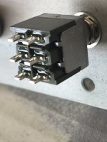
It is likely that the switch pictured has one side that is normally closed and the other that is normally open. You would want to connect to the normally open side so that when you push the button it momentarily closes the circuit.
The other side would be opposite, ie the circuit would always be grounded UNTIL you push the button, then it would open.
Easy to check with a meter...
There was a thread on this, I think.
It is a DP switch because there are two separate circuits.
One goes to the GMC507 and I think the other is for the navigator...both are momentary ground when the button is pressed. At least that's how my diagram says it's wired...
It should give you TOGA pitch and roll on your PFD and the one connected to the GTN sequences the missed approach...
When I wired mine, the TOGA switched Grd went to a discrete input, not to the 307. Maybe the 507 has a dedicated TOGA input that the 307 didn't. Also, the GNS4xx series don't get a TOGA source, only the newer navigators. It's interesting that the OPs diagram shows the ID Program pin going to grd through the TOGA switch. I didn't do that and don't recall seeing that in the manual. Did I miss something?
Larry
Last edited:
Thanks Bob. I am trying to figure out if the switch grounds both inputs out at the same time. I got 3 wires to attach and one jumper to ground, but which lugs do the wires go to?
Bob is correct, but I am not sure if it applies if you have other than a 650, like a 430W.
Garmin says to wire each separate to the ground but both need to be grounded at the same time. Mine is a single pole which has both of them connected to the same pole and grounds at the same time. I have never had any issues with it.
As for what it does, it is Go Around switch if you are coupled to the auto pilot. One main function/use is for missed approach. Pushing this button will execute the miss approach and the auto pilot will fly the miss.
rocketman1988
Well Known Member
...and
Yes, there was a thread on connecting bot to on terminal. I seem to recall that the Garmin Expert had some reason for not connecting the two wires together...
Yes, there was a thread on connecting bot to on terminal. I seem to recall that the Garmin Expert had some reason for not connecting the two wires together...
Longez
Well Known Member
Yes, there was a thread on connecting both to one terminal. I seem to recall that the Garmin Expert had some reason for not connecting the two wires together...
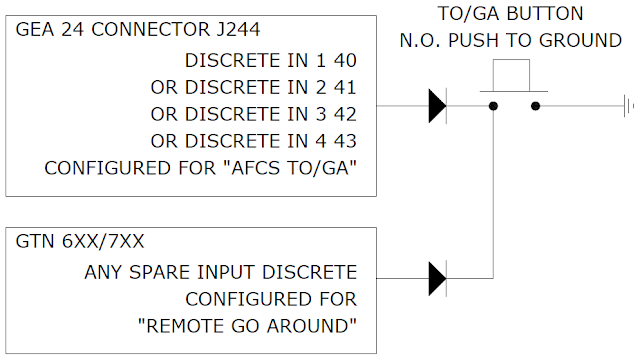
It is ok to connect both inputs to a SPST button/switch if diodes are used to isolate the 2 inputs.
This applies both when using the GEA 24 or the GMC 507 TO/GA input in combination with the navigator input.
Most new installations now have a GMC 507 which provides the TO/GA input and frees up another discrete input on the GEA 24.
A little more information in this thread/posting: https://vansairforce.com/community/showpost.php?p=1377917&postcount=16
Steve
Longez
Well Known Member
I have a GTN 650 with a 307. The drawing is from Steinair, as is the TO/GA switch so I assume it it correct. The switch and the 6 lugs is what befuddles me though. I'll get the meter out and start testing I guess.?
Not sure why you have a DPDT switch as opposed to the DPST switch shown on Stein's website, but it should still work fine.
The DPDT switch will have 2 common poles, 2 NO poles, and 2 NC poles. Just wire up the 2 common poles and the 2 NO poles like shown on your wiring diagram.
Steve
TOGA Switch
David,
Wiring a DPST TO/GA switch to both your GTN and G3X Touch will allow you to make the most of the integration that is possible between your EFIS, Autopilot and Navigator. When the switch is pressed, it simultaneously grounds an input on both the G3X Touch and GTN to help reduce pilot workload through the missed approach procedure.
By grounding the input on the G3X Touch, the autopilot sequences to GA mode both vertically and laterally. Vertically, the aircraft will pitch up to a pre-programmed pitch attitude for climb out, and will remain in that pitch attitude until your pre-programmed missed approach altitude is reached. Laterally, it will hold wings level.
By grounding the input on the GTN, the flight plan will sequence to the first waypoint in the missed approach procedure. Depending on where you are in the approach, at a certain point, GA mode, which is holding the wings level laterally will automatically switch back to GPS mode and begin navigating to the first missed approach waypoint.
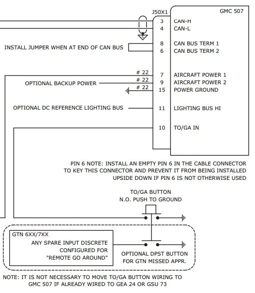
The GMC 507 has a dedicated TO/GA input, so the DPST switch is wired directly to the Mode controller. To clear up any confusion, using a discrete input on a GEA 24 will also work for this purpose, if programmed to AFCS TO/GA - Active Low.
This video includes a good demonstration of a simulated missed approach procedure with the G3X Touch.
Thanks,
Justin
David,
Wiring a DPST TO/GA switch to both your GTN and G3X Touch will allow you to make the most of the integration that is possible between your EFIS, Autopilot and Navigator. When the switch is pressed, it simultaneously grounds an input on both the G3X Touch and GTN to help reduce pilot workload through the missed approach procedure.
By grounding the input on the G3X Touch, the autopilot sequences to GA mode both vertically and laterally. Vertically, the aircraft will pitch up to a pre-programmed pitch attitude for climb out, and will remain in that pitch attitude until your pre-programmed missed approach altitude is reached. Laterally, it will hold wings level.
By grounding the input on the GTN, the flight plan will sequence to the first waypoint in the missed approach procedure. Depending on where you are in the approach, at a certain point, GA mode, which is holding the wings level laterally will automatically switch back to GPS mode and begin navigating to the first missed approach waypoint.
The GMC 507 has a dedicated TO/GA input, so the DPST switch is wired directly to the Mode controller. To clear up any confusion, using a discrete input on a GEA 24 will also work for this purpose, if programmed to AFCS TO/GA - Active Low.
This video includes a good demonstration of a simulated missed approach procedure with the G3X Touch.
Thanks,
Justin
Not sure why you have a DPDT switch as opposed to the DPST switch shown on Stein's website, but it should still work fine.
The DPDT switch will have 2 common poles, 2 NO poles, and 2 NC poles. Just wire up the 2 common poles and the 2 NO poles like shown on your wiring diagram.
Steve
Sorry, yes my switch is DPST from Steinair.
Alright,,,thanks everyone. I got it now. I thought I had a DPDT switch but I took another look at Steins website and sure enough,, its a DPST switch!
Best to check it first. A DPST typically has 4 terminals and a DPDT has 6.
BillL
Well Known Member
Adding to the original post's request for "what should it do?," I would add that it should command the flaps to move to take-off position, on aircraft with electric flaps.
You are just going to confuse the guy. We should talk about what it does.
What it does is complicated enough to sort when going missed on an ILS vs RNAV approach and what to expect the AP to do.
AND - it only works with a GMC 30X, 50X panel installed. I have a nice button installed and checked but with the G3X 37X and no GMC. It will not initiate functions.
Yes. That's what it does in my friend's Rocket.You are just going to confuse the guy. We should talk about what it does.
The OP didn't ask what it does on a specific system. He asked what the TOGA switch does generally. In General, the TOGA switch is a one-push (or one toggle) switch that resets everything for takeoff/go around. That means everything it possibly can, to reduce the pilot's workload. There's no reason that anything servo-driven couldn't be part of this.
Just reviving this thread to add a query, as I can’t find the manual for the GNX375 online.
For an install with a GMC507/GNX375, do they also need a seperate to/ga input via a DPST button? The g3x manual doesn’t really show how this works - only how to wire it with a GTN.
Or can I wire a to/ga button to just the GMC507 autopilot controller and it will let the gnx375 know to go around via canbus or the rs232 connection between the gdu/gnx
I ask as I was considering using the momentary push button on my stick for to/ga. But if it needs to be dual pole, this won’t work. Or, I could use diodes i suppose.
Why does the TO/GA need to go to two devices via a DPST anyway? After all, both the devices would be grounded to the same place anyway. So grounding both TO/GA pins through the same switch to a common ground shouldn’t be an issue?!
For an install with a GMC507/GNX375, do they also need a seperate to/ga input via a DPST button? The g3x manual doesn’t really show how this works - only how to wire it with a GTN.
The Garmin 2" navigators (GPS 175 / GNC 355 / GNX 375) also have a discrete input for "remote go-around", so yes if you want this capability you will need to follow the same guidance as for a G3X+GTN installation, with the appropriate pin.
Or can I wire a to/ga button to just the GMC507 autopilot controller and it will let the gnx375 know to go around via canbus or the rs232 connection between the gdu/gnx
No, as far as I'm aware, none of these navigators have the ability to accept a remote command to activate a missed approach procedure except via a discrete input.
I ask as I was considering using the momentary push button on my stick for to/ga. But if it needs to be dual pole, this won’t work. Or, I could use diodes i suppose.
Yes, you could use a pair of diodes with the cathodes connected together. I imagine they specifiy a dual-pole switch in the manual because it's easier to explain.
Why does the TO/GA need to go to two devices via a DPST anyway? After all, both the devices would be grounded to the same place anyway. So grounding both TO/GA pins through the same switch to a common ground shouldn’t be an issue?!
Typically this is done so that when one device is turned off it doesn't inadvertently pull the input of the other device to ground. Separate switches or a pair of diodes will prevent this.
TO/GA Switch Wiring
The GEA24 and GMC507 are both capable of providing the TOGA input for the G3X portion of the system and there are no functional differences between these inputs. This just takes up one of your discrete spots, but it looks like that isn't an issue with your system.
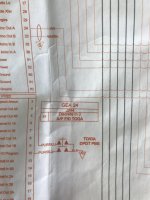
I whipped up a quick detail drawing on how to wire this switch per your avionics drawing. Please note that the purple/blue wires should be connected to the posts labeled "NO" (normally open), not the posts labeled "NC" (normally closed). You can see these labels on the picture of the switch you posted. You will also want the two common posts to go to ground. I find it is easiest to do this by using a jumper at the switch and running a single wire to the ground block.
The GEA24 and GMC507 are both capable of providing the TOGA input for the G3X portion of the system and there are no functional differences between these inputs. This just takes up one of your discrete spots, but it looks like that isn't an issue with your system.
I whipped up a quick detail drawing on how to wire this switch per your avionics drawing. Please note that the purple/blue wires should be connected to the posts labeled "NO" (normally open), not the posts labeled "NC" (normally closed). You can see these labels on the picture of the switch you posted. You will also want the two common posts to go to ground. I find it is easiest to do this by using a jumper at the switch and running a single wire to the ground block.
Attachments
Alright,,,thanks everyone. I got it now. I thought I had a DPDT switch but I took another look at Steins website and sure enough,, its a DPST switch!
Looks like we had a mistake on our website... It is a DPDT momentary push button switch. I just corrected this. Sorry for the additional confusion.
Typically this is done so that when one device is turned off it doesn't inadvertently pull the input of the other device to ground. Separate switches or a pair of diodes will prevent this.
Thanks for your detailed response.
I still can’t get my head around this tho. Both devices would have their ground pins connected to the battery ground. Are you staying when a box turns off, the to/ga pin would be internally connected to the ground pin in that device? (Essentially giving a to/ga discrete to the other box)
Last edited:
I still can’t get my head around this tho. Both devices would have their grounds connected. Everything in the aircraft will have the same ground potential!
I don't have the exact internals of the discrete inputs on either of these devices in front of me, but speaking generally from past experience: typically there will be an internal pull-up resistor, which can become a pull-down resistor when the device's power supply goes away.
I don't have the exact internals of the discrete inputs on either of these devices in front of me, but speaking generally from past experience: typically there will be an internal pull-up resistor, which can become a pull-down resistor when the device's power supply goes away.
Thanks Matt.
I searched “diode” at my local electronics shop and there are predictably a lot of results!! The g3x manual doesn’t help much except shows a zener diode and a normal diode used in a rotax install.
Would something like this do the job? (Good for 450ma)
https://www.jaycar.com.au/1n4148-1n914-signal-diode-pack-of-5/p/ZR1100
When using a double pole switch, like the one you got from us, no diodes are required. The reason we use a double pole switch is to isolate those two circuits from each other- the same thing you would be using the diodes for.
EDIT: sorry, didn't read far enough back. Matt is absolutely correct, if putting this on the stocks you will want to use signal diodes to isolate the units from each other. he is correct that if one unit fails it could pull the other to ground causing the go around switch to be stuck. If you want to do this, with or without a TOGA switch on the panel let me know and I'll update that drawing for whatever configuration you want to use.
Last edited:

