What's new
Van's Air Force

Don't miss anything! Register now for full access to the definitive RV support community.

Ground

wirejock

Well Known Member
Something to think about.
I see so much discussion about redundant power. Alternators, batteries, etc.

Today, I got a real scare. Thankfully my airplane isn't flying and it's a relatively easy fix. I won't go into details. That's not the point. Suffice to say, ground came loose just enough to wreak havoc. Half the panel crashed. No idea what actually would function. Some stuff was still on. I plan to test that senario later.

The point is, nobody talks about ground redundancy. I'm sure I don't understand, but what happens if the ground fails?
Dont those electrons need ground? I don't read anyone planning a secondary ground path. Maybe because of ground loops and such. Anyway. I thought it important enough to at least post and start a discussion.

I've worked on enough cars that I knew it was a ground problem when it went Tango Uniform, but that would be of no value in the air. I definately need to plan for a totally separate thingamagigger.
 
A lot of avionics have secondary grounding through the chassis as well.
Ive never considered a ground any more important than power at the component level.
At the bus level it doesn’t matter as the whole airframe is the ground and therefore you can’t have a failure other than the airframe to the battery or the other important one which is the engine to airframe. I have duplicated that one.
Be interested to see what others think.
 
...

The point is, nobody talks about ground redundancy. I'm sure I don't understand, but what happens if the ground fails?
Dont those electrons need ground? I don't read anyone planning a secondary ground path. Maybe because of ground loops and such. Anyway. I thought it important enough to at least post and start a discussion.
...

Actually, lots of people talk about redundant ground paths, not the least of which is Bob Nuckolls and Stein.

https://www.kitplanes.com/ground-control/

https://www.kitplanes.com/best-practices-electrical/

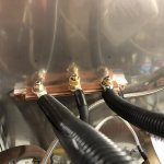
Here's how I did it:

http://www.rv8.ch/ground-point-on-firewall/


img_2648.jpg
 
Hey Larry-

Are you talking about like a forest of tabs coming loose or a battery cable or what?

No matter how well you design something, at some point you're gonna get to a single point failure scenario. You just have to decide when your mitigation strategies have pushed that possibility back far enough for a reasonable level of safety.

It was the ground cable to my Advanced Control Module. I purposely redacted the issue because I wanted the discussion to focus and not offer opinions on my design. That's not the point. It's about single point of failure ground.

I started the discussion with AFS to understand why my particular problem preciptated the failures. I need to understand what happens when things fail.

As mentioned, every system has a single point of failure. The trick is to identify it, test and prepare should the it happen. That is the purpose of my post. I missed this one and I'm glad she was in the garage when it happened.
 
Risk Management

A failure of almost any conductor in our planes will result in some type of system failure. The big kids use a risk matrix to decide if a potential problem needs to be addressed.

https://safetyculture.com/topics/risk-assessment/5x5-risk-matrix/

I was raised on to the 5x5 matrix and use it for every safety related decision. You don’t have to be that rigorous but The basic premise is to decide what the impact of a failure is and the probability of it happening. A properly sized wire terminated and strain relieved in your panel should last the life of the airplane. The ground to the engine is different. A failure is more probable because it’s tied to a vibrating engine and if it fails the damage to the alternate return path can be serious. Using a redundant ground makes sense.

If you use redundant conductors for everything you are carrying around twice as much wire as you need and you have no way to test if one is working.
 

Attachments

  • IMG_0405.jpeg
    IMG_0405.jpeg
    83.5 KB · Views: 53
Last edited:
help me understand...which part of the ground are you doubling for redundancy?
Is this about the connection from the engine to the airframe or ground bus?
or about the connection from the battery post to the airframe/ground bus?
 
help me understand...which part of the ground are you doubling for redundancy?
Is this about the connection from the engine to the airframe or ground bus?
or about the connection from the battery post to the airframe/ground bus?

I have two braided ground straps from the engine to the grounding bus on the firewall. The connections to the engine are in two different places. I think this is sole point of redundancy that I built in the airplane. The rationale is to keep the engine running, not sure if this makes sense to me either. I didn't try to do to much else since it's a daytime VFR airplane.
 
None of use will ever eliminate every single point failure risk in our planes. But, we can mitigate the result.

For the engine ground I never considered multiple engine grounds a good idea. If the engine ground fails, the engine does not start. You find this out on the ground - so risk is mitigated. Just be careful you do not have any “phantom” grounds that could provide a return path to the panel for starter current.

Side note - I use the same #2 welding wire as the engine ground as the power to the starter (the component using the current). The ground wire goes to the nice ground lug on the starter. I never liked braided ground straps going to some greasy bolt on the engine. I really don’t like the RV-14 “ground via the engine mount” approach.

For the panel I identify the single point failure risks and I evaluate the impact on continued IFR flight. I run two PC-625 batteries, each feeding half the panel (power and ground), two master solenoids and the panel power comes from the battery side of the master solenoids via 30 amp relays. EFIS #1, Nav #1, Comm #1, etc. comes from one battery/ground combination. EFIS #2, Nav #2, Comm #2 comes from the other battery/ground combination. For any reasonable electric failure at bare minimum half the panel is available, more than adequate for continued IFR flight.

Carl
 
Ground path

I have two braided ground straps from the engine to the grounding bus on the firewall. The connections to the engine are in two different places. I think this is sole point of redundancy that I built in the airplane. The rationale is to keep the engine running, not sure if this makes sense to me either. I didn't try to do to much else since it's a daytime VFR airplane.

That's interesting because the P-Mag destructions talk about the ground going to the same point as the engine ground. I assume to eliminate multiple ground paths.
When I was installing engine grounds. Most of the threads I found, recommended a single ground from FOT to engine case. The starter would get it's ground through the case. Ok. So why does every car I've ever worked on have the main ground terminated at the starter/engine bolt.
This stuff makes my brain hurt. Short trip. Time for Advil again.
 
...

For the engine ground I never considered multiple engine grounds a good idea. If the engine ground fails, the engine does not start. You find this out on the ground - so risk is mitigated. Just be careful you do not have any “phantom” grounds that could provide a return path to the panel for starter current.
...

From what I've read, almost everything wired to the engine will become the ground path if you lose your single engine ground, which is why 2 grounds are recommended by a lot of experts.

Your engine probably won't start if your single ground path fails, but when you do try to start it, you will send a lot of current through cables, sensors, p-leads, and anything else that might allow an electron to flow - possibly damaging them.
 
... So why does every car I've ever worked on have the main ground terminated at the starter/engine bolt.
...

The car guys do this because they have millions of hours of experience in building reliable systems. Notice that over time, experimental aviation picks up many of the good practices we learn from the automotive world. In aviation, we need our systems to be light and simple and reliable, but if we have to choose one, it would be reliable.
 
Rivets as ground path

OK, so my RV-4, even though first flight was in 2021, was a project where fuselage (firewall) was probably mainly riveted in the 90's.

I know there are a lot of rivets from the SS firewall to skins and longeron angles, but how well do those do over time as ground paths?

My common ground point for the airframe is a SS screw through the firewall -- forest of tabs on cockpit side and maybe 4" of 8 AWG to battery negative pole on engine side. Flexible ground strap from battery negative to engine block near alternator. Also ground path from engine via engine mount to airframe. No problems with ground voltage drop when starting.

Using airframe as ground for some items like flap motor, lights and antennas.

Finn
 
The car guys do this because they have millions of hours of experience in building reliable systems. Notice that over time, experimental aviation picks up many of the good practices we learn from the automotive world. In aviation, we need our systems to be light and simple and reliable, but if we have to choose one, it would be reliable.

I have seen a lot of cars and most just pick a spot on the engine block that is close to the battery, to minimize cable length. Seen very few where they extend the cable to make the attach point close to the starter. The block has no resistance, so ground point can be anywhere. All the problems will come from issues where the terminal attaches to the block. That is usually the weak point, as is a cable corroding under the insulation.
 
Where the grounding strap connects, should dielectric grease or something else be used?
 
Soap Box...

I'm concerned about a trend that I see developing -- it seems that too much emphasis is being placed upon recovering from a fault by adding redundancy, instead of determining true root causes of failures (to which MikeyB alluded) and mitigating them (eliminating them).

The strategy of "I'm gonna add another [insert thing here] for redundancy..." is not a good approach if the [insert thing here] isn't a high quality/fidelity part to begin with...

Said differently, adding another crummy ground path (bad termination, wrong wire size & type) to an already existing crummy ground path accomplishes nothing.

Apologies if I offended anyone -- that's not my intention.
 
That's interesting because the P-Mag destructions talk about the ground going to the same point as the engine ground. I assume to eliminate multiple ground paths. SNIP

The reasoning is that if the pMag is grounded someplace other than the engine, you add a risk of loss of engine. The pMags create their own power just like your alternator. The output of the pMag must be against engine ground - as are your spark plugs.

From the install manual:

Pin “1” connects directly to a nearby engine case ground using 18 gauge wire. Note: You cannot rely on the ignition’s mechanical attachment to the engine to provide ground. Aluminum anodizing acts as an electrical insulator, so the clamp connection to the anodized flange will not be a reliable ground.

Carl
 
It was the ground cable to my Advanced Control Module. I purposely redacted the issue because I wanted the discussion to focus and not offer opinions on my design. That's not the point. It's about single point of failure ground.

It's about design. It's a one-box-controls-everything system. The single point is the box. No box, no issue.

I'm concerned about a trend that I see developing -- it seems that too much emphasis is being placed upon recovering from a fault by adding redundancy, instead of determining true root causes of failures (to which MikeyB alluded) and mitigating them (eliminating them).

Yep.
 
Last edited:
The reasoning is that if the pMag is grounded someplace other than the engine, you add a risk of loss of engine. The pMags create their own power just like your alternator. The output of the pMag must be against engine ground - as are your spark plugs.


Carl

Pmags don't really use a typical ground path for sparking. I believe they use wasted spark coils (if that is incorrect, please disregard). Wasted spark coil are double tapped and have no connection to the ground plane, unlike traditional coils. the energy from the collapsing secondary winding flows to one of the two center electrodes, jumps the gap to the base, then goes to the block, then to the opposing sparkplug ground electrode, jumps that gap and then flows back to the other side of the coil, completing the circuit. The energy flow back through the opposing tap on the winding, not through a common ground. On my EI, the wasted spark coils are completely isolated from any ground outside of that made with the sparkplugs.

That is for the secondary winding. To charge the coil on the primary winding, yes you need a good ground; at least if running ship power. The pmag shouldn't need an external ground if it is generating it's own power, as it is all self contained and should be able to perform even if isolated from a ground plane. At least in theory, if it was designed correctly. This is what a mag does. requires no ground to operate, assuming the shielded cables are used (shields become ground return path for the spark instead of the block). This is how people get shocked when playing with mags that aren't even connected to an engine or other ground plane. I often test mags on my lathe. Chuck up the gear and spin. The sparkplug that is hanging in free air starts sparking.
 
Last edited:
Back
Top