I am beginning the installation of a GPS 175 in an RV-6. Does anyone have experience with mounting the GA35 on the glareshield ? I have the Dynon GPS 2020 antenna and ELT antenna mounted aft of the canopy, and don’t want to mount it there. I don’t really want to go in front of the windscreen. The glareshield (upper fuselage skin) just inside the windscreen seems like a possible choice. Anyone with experience with it there?

Van's Air Force
You are using an out of date browser. It may not display this or other websites correctly.
You should upgrade or use an alternative browser.
You should upgrade or use an alternative browser.
GPS 175 antenna mounting location
- Thread starter RVDan
- Start date

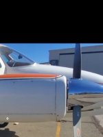
I added the GA-35 antenna for my GPS-175 just aft of the Dynon GPS and ELT antenna on the aft top fuselage skin. It is probably the best location for following Garmin's mounting instructions. In IFR, you really want to have a reliable view to the GPS constellation. I did have to fabricate a doubler, but that was fairly easy to make and install.

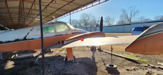
Rough position on the upper aft fuselage behind the ELT antenna.
Rough position on the upper aft fuselage behind the ELT antenna.
Dan,I am beginning the installation of a GPS 175 in an RV-6. Does anyone have experience with mounting the GA35 on the glareshield ? I have the Dynon GPS 2020 antenna and ELT antenna mounted aft of the canopy, and don’t want to mount it there. I don’t really want to go in front of the windscreen. The glareshield (upper fuselage skin) just inside the windscreen seems like a possible choice. Anyone with experience with it there?
On my Wittman Tailwind, I mounted my GPS 175 antenna on the glare shield and it has been rock solid during all phases of IFR flight. It is about half way back from the front of the windscreen to the face of the panel. Since I have some ferrous metal fuselage tubes in that area, I was originally concerned but it has been working perfectly.
Keith
I added the GA-35 antenna for my GPS-175 just aft of the Dynon GPS and ELT antenna on the aft top fuselage skin. It is probably the best location for following Garmin's mounting instructions. In IFR, you really want to have a reliable view to the GPS constellation. I did have to fabricate a doubler, but that was fairly easy to make and install.
Rough position on the upper aft fuselage behind the ELT an
I have installed the GA35 on four aircraft on their glareshields and they have performed well; two were RV's with aluminum glareshields, and the other two had fiberglass. The fiberglass has to have a ground plane under it with a radius of 7.5 inches. The manual says it can be heavy duty foil tape, but I used some thin aluminum sheet, and had the screws from the GA35 bonded to it. One was a VFR install and I could not get the full 7.5 radius for the ground plane, so I made it a bit narrower and wider to fit, and it worked well. I painted them all with flat black non-metallic spray paint; Just make sure you have the correct length of coax going to them and you should be good.I am beginning the installation of a GPS 175 in an RV-6. Does anyone have experience with mounting the GA35 on the glareshield ? I have the Dynon GPS 2020 antenna and ELT antenna mounted aft of the canopy, and don’t want to mount it there. I don’t really want to go in front of the windscreen. The glareshield (upper fuselage skin) just inside the windscreen seems like a possible choice. Anyone with experience with it there?
Off topic, but that paint looks amazing!I added the GA-35 antenna for my GPS-175 just aft of the Dynon GPS and ELT antenna on the aft top fuselage skin. It is probably the best location for following Garmin's mounting instructions. In IFR, you really want to have a reliable view to the GPS constellation. I did have to fabricate a doubler, but that was fairly easy to make and install.
Rough position on the upper aft fuselage behind the ELT antenna.


mine is also about 6 inches back from the dynon gps . possibly not the ideal location after reading some reports about oscillation in GA35 taking out all nearby GPS receivers. If I lose the gps signal abruptly powering off the garmin gps/antenna would be on top of the list.the GA-35 antenna for my GPS-175 just aft of the Dynon GPS
Before you mount the GPS antenna anywhere like the glare shield or forward, find out if the GPS-175 shares the same malady as the GTN-650 for comm radio high frequency harmonics wiping out the all satellite signals when transmitting. If so, mount it aft of the cockpit on top of the fuselage. Here the extra coax length to the GPS antenna is your friend.
The SkyView GPS antenna is a happy camper on the glare shield. Just remember to cover it with some dark cloth to eliminate glare on the windshield.
Carl
The SkyView GPS antenna is a happy camper on the glare shield. Just remember to cover it with some dark cloth to eliminate glare on the windshield.
Carl
Before you mount the GPS antenna anywhere like the glare shield or forward, find out if the GPS-175 shares the same malady as the GTN-650 for comm radio high frequency harmonics wiping out the all satellite signals when transmitting. If so, mount it aft of the cockpit on top of the fuselage. Here the extra coax length to the GPS antenna is your friend.
The SkyView GPS antenna is a happy camper on the glare shield. Just remember to cover it with some dark cloth to eliminate glare on the windshield.
Carl
...just buy one of these in any case...

Ted 4-70 GPS Notch Filter | Aircraft Spruce ®
Ted 4-70 GPS Notch Filter Your global positioning system receives its positional information at 1575.42 megahertz. The communications radios on-board your aircraft typically broadcast in the 121.5 megahertz range.
Following the imanual is a good place to start:Before you mount the GPS antenna anywhere like the glare shield or forward, find out if the GPS-175 shares the same malady as the GTN-650 for comm radio high frequency harmonics wiping out the all satellite signals when transmitting. If so, mount it aft of the cockpit on top of the fuselage. Here the extra coax length to the GPS antenna is your friend.
The SkyView GPS antenna is a happy camper on the glare shield. Just remember to cover it with some dark cloth to eliminate glare on the windshield.
Carl
"The installation guidelines meet the intent of AC 20-138D chapter 13. The greater the deviation from these guidelines,
the greater the chance of decreased signal quality and availability. It is possible that all of the installation guidelines
cannot be met. These guidelines are listed in order of importance to get the best performance. The installer should use
best judgment to balance the installation guidelines."
6.3.1 Antenna Location
The GPS antenna should:
1. Be installed as near to level as possible with respect to the normal cruise flight attitude of the aircraft.
2. Be installed in a location to minimize the effects of airframe shadowing during typical maneuvers.
3. Be installed a minimum of two feet from any VHF COM antenna or any other antenna which may emit harmonic
interference at the L1 frequency of 1575.42 MHz.
4. Be installed a minimum of two feet from any antennas emitting more than 25 watts.
5. Be installed a minimum of nine inches (center to center) from other antennas, including passive antennas such as
another GPS or XM antenna.
6. Be installed a minimum of three inches from the windscreen.
7. Have a twelve inch center to center spacing between GPS antennas.
You would think a $12K GTN-650 would incorporate this solution to their known problem…...just buy one of these in any case...
Ted 4-70 GPS Notch Filter | Aircraft Spruce ®
Ted 4-70 GPS Notch Filter Your global positioning system receives its positional information at 1575.42 megahertz. The communications radios on-board your aircraft typically broadcast in the 121.5 megahertz range.www.aircraftspruce.com
Carl
If you mount the antenna where it belongs and use good coax/connectors you wouldn't have that problemYou would think a $12K GTN-650 would incorporate this solution to their known problem…
Carl
")
SuperCubDriver
Well Known Member
I mounted mine under the cowling close to the firewall. It works great but the location is not recommended by Garmin. I copied this from other builders and so far have no complaints.
I have mine under cowl also right next to the Dynon gps antennaHave you considered a shelf under the cowl, many have done that and I have mine there (GNX375) and it works fine.
Figs

Thanks for the comment. I gave this some thought, but not something I really want to do. I would have to relocate existing stuff and it blocks access.Have you considered a shelf under the cowl, many have done that and I have mine there (GNX375) and it works fine.
Figs
I like this idea and will see if it works.The following 1.) Can't possibly work, 2.) Will not work when you need it the most, 3.) Will cause death & destruction, and 4.) Is specifically banned in Canada...
View attachment 74769
Note that the 3 inches from the windscreen applies to roof mounting where you would be mounting the antenna just aft of the windscreen. They want a ground plane to extend at least 3”.Following the imanual is a good place to start:
"The installation guidelines meet the intent of AC 20-138D chapter 13. The greater the deviation from these guidelines,
the greater the chance of decreased signal quality and availability. It is possible that all of the installation guidelines
cannot be met. These guidelines are listed in order of importance to get the best performance. The installer should use
best judgment to balance the installation guidelines."
6.3.1 Antenna Location
The GPS antenna should:
1. Be installed as near to level as possible with respect to the normal cruise flight attitude of the aircraft.
2. Be installed in a location to minimize the effects of airframe shadowing during typical maneuvers.
3. Be installed a minimum of two feet from any VHF COM antenna or any other antenna which may emit harmonic
interference at the L1 frequency of 1575.42 MHz.
4. Be installed a minimum of two feet from any antennas emitting more than 25 watts.
5. Be installed a minimum of nine inches (center to center) from other antennas, including passive antennas such as
another GPS or XM antenna.
6. Be installed a minimum of three inches from the windscreen.
7. Have a twelve inch center to center spacing between GPS antennas.
Well - they do document it in the docs...but, yeah....You would think a $12K GTN-650 would incorporate this solution to their known problem…
Carl
I've installed a lot of 2" GPS receivers recently (GNX 375) in composite airframes that have a KX165A nav/com. The routing of the GPS coax relative to the nav/com is key, as is the quality of the coax (RG400) and the terminations. The GPS and com antennae are a long way apart. Occasionally transmitting on the Garmin test frequencies just shuts down GPS reception immediately. Installing an overhauled nav/com is sometimes the only remedy. This isn't just a GTN 650 problem.
why would an overhauled navcom be affect the gps signal different than a non overhauled? Is it the location of the actual antenna or the coax line also that must not be near the navcom antenna or coax line?I've installed a lot of 2" GPS receivers recently (GNX 375) in composite airframes that have a KX165A nav/com. The routing of the GPS coax relative to the nav/com is key, as is the quality of the coax (RG400) and the terminations. The GPS and com antennae are a long way apart. Occasionally transmitting on the Garmin test frequencies just shuts down GPS reception immediately. Installing an overhauled nav/com is sometimes the only remedy. This isn't just a GTN 650 problem.
My kx155 is directly under my gps175, the antenna cables are less than 2 inches apart off the units, after the cables exit the boxes I can keep them apart, but out of the radios themselves they will be close, the navcom sits under the gps in the stack
Harmonics, sometimes a result of output circuit tuning in those old radios.An olt transmitter could be transmitting off frequency or with an unstable carrier. These would show up in a bench check of the transmitter.
The following 1.) Can't possibly work, 2.) Will not work when you need it the most, 3.) Will cause death & destruction, and 4.) Is specifically banned in Canada...
View attachment 74769
I like this idea and will see if it works.
Yea it is nice. On a new build sure. However on an already flying airplane good luck cutting those access holes, reinforcing them, making fiberglass panels. Did you not read the warning it is illegal in 6 of 7 Continents and might cause cancer. I am kidding. I like that approach (no pun intended) but it's "Bookoo" work (anglicized French word beaucoup for "a lot). I really can't see crawling up in there to install this. New build yes, sure why note, will work well last a long time (unless rain leaks around that cover). Existing plane with panel installed and not coming out, that looks like a nightmare retro fit.
So you are left with the back of the airplane atop fuselage (traditional logical and will work well) and long coaxial run. Glare shield and seeing that hump and if slider the frame may interfere a tad wee bit. Last engine compartment will make Garmin sad and heat is no doubt not great for it, but people seem to have good success there.
I have a GPS175. Great unit and a bargain in the arm and a leg prices of things today.
I have an old 310B and have two comm ants on the top fuselage so no way to keep the gps ant 3 feet from either comm ant, so out on the wing my gps175 ant goes. I have an inspection panel about a foot square outboard of the right engine that gets the holes drilled and the gps ant mounted, also have a spare panel from my parts plane so can pop the panel off and disconect the antenna in about one minute and put the spare panel with no holes on when Im traveling.
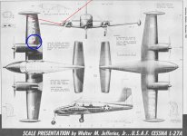
Will be about where the red dot is in this pic. Should work fine out there, its well aft of the leading edge, around 60 maybe 70 percent back on the chord, and inboard of the aileron. The flaps are split so not going to affect any aero flow over those.
Will be about where the red dot is in this pic. Should work fine out there, its well aft of the leading edge, around 60 maybe 70 percent back on the chord, and inboard of the aileron. The flaps are split so not going to affect any aero flow over those.
Attachments
Last edited:
Carl beat me to the answer yet again.Before you mount the GPS antenna anywhere like the glare shield or forward, find out if the GPS-175 shares the same malady as the GTN-650 for comm radio high frequency harmonics wiping out the all satellite signals when transmitting. If so, mount it aft of the cockpit on top of the fuselage. Here the extra coax length to the GPS antenna is your friend.
The SkyView GPS antenna is a happy camper on the glare shield. Just remember to cover it with some dark cloth to eliminate glare on the windshield.
Carl
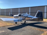
Carl directed my GPS-175 install in my -6A. It is aft on the fuselage, and the Dynon is forward on the glare shield. They work without interference. From the install manual:
The Garmin has a minimum length on the antenna cable
RG-400 is used, it must be between6.5 and 35 feet long to meet the cable loss requirement.
It recommends protection from heat and power, so on the engine side of the firewall is not suggested.
Although not the best picture, both are visible on my plane. The Garmin is just under the slider when pulled back.
Just my 2 cents.
Daddyman58
Attachments
I have an old 310B and have two comm ants on the top fuselage so no way to keep the gps ant 3 feet from either comm ant, so out on the wing my gps175 ant goes. I have an inspection panel about a foot square outboard of the right engine that gets the holes drilled and the gps ant mounted, also have a spare panel from my parts plane so can pop the panel off and disconect the antenna in about one minute and put the spare panel with no holes on when Im traveling.
Will be about where the red dot is in this pic.
I'd be very hesitant to mount a GPS antenna in that location, as it will have significant airframe shadowing issues. If you don't want to relocate any transmitting antennas, then I would instead suggest looking at one of the Comant GPS/VHF combo antennas.
Thanks will have to see, there will be some shadowing from the engine exhaust nacelle, should have a clear view of front and back and right side, but that left side will have shadowing, the exhaust nacelle is about 4 inches high there and about 8 inches from the antenna. The antenna will be where the red dot is inside the blue circle.I'd be very hesitant to mount a GPS antenna in that location, as it will have significant airframe shadowing issues. If you don't want to relocate any transmitting antennas, then I would instead suggest looking at one of the Comant GPS/VHF combo antennas.
Its been maintaining the WAAS signal just laying inside the cockpit on top of the glareshield, but the windshield is raked back quite a bit on the early 310, has a good view of all sats in front and off to the sides but not behind.
Edit, looking closer that is more shadow than I thought, everything on the left side crosshatched in yello from the horizon up to about 45 degrees will be shadowed
I just read an article about not having the comm and gps antennas close, how do the comm/gps combo ants work? Must have a built in notch filter like someone mentioned https://www.aircraftspruce.com/catalog/avpages/tednotch.php there only 127 bucks, guess I could mount the gps ant right between the two comm ants and get the notch filter
.
Attachments
Last edited:
To me, the bigger problem here is the mask that's being created *on all sides* by submerging the antenna into a pocket. Granted, a FF installation will have some masking to the rear, by the firewall, but if mounted as close as possible to the cowling and at least a few inches forward, that's minimized. This installation creates a solid mask for the entire 360 degrees of azimuth.Yea it is nice. On a new build sure. However on an already flying airplane good luck cutting those access holes, reinforcing them, making fiberglass panels. Did you not read the warning it is illegal in 6 of 7 Continents and might cause cancer. I am kidding. I like that approach (no pun intended) but it's "Bookoo" work (anglicized French word beaucoup for "a lot). I really can't see crawling up in there to install this. New build yes, sure why note, will work well last a long time (unless rain leaks around that cover). Existing plane with panel installed and not coming out, that looks like a nightmare retro fit.
So you are left with the back of the airplane atop fuselage (traditional logical and will work well) and long coaxial run. Glare shield and seeing that hump and if slider the frame may interfere a tad wee bit. Last engine compartment will make Garmin sad and heat is no doubt not great for it, but people seem to have good success there.
I have a GPS175. Great unit and a bargain in the arm and a leg prices of things today.
Does the antenna work under fiberglass, might mount the antenna under the fiberglass cone that screws onto the back of my wingtip if that will work, that way no drilling, thats just a fiberglass cone that screws onto the back of the wingtip tank and should hardly be anymore shadowing than when mounted on top of the fuselage, some forward satellites may not be seen. This is not my 310 but one I found like mine on the internet showing the cone


I wouldn't recommend this.might mount the antenna under the fiberglass cone that screws onto the back of my wingtip
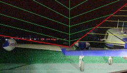
[sigh] I see a lack of understanding of the basic math geometry here. At the circled-in-blue location, the airframe blocks nearly half of the close to the horizon solid angle. This is exactly where gps satellites are more likely to be. Furthermore, it is these satellites that have the best geometry for determining your position. Satellites that are straight overhead are great for figuring out your altitude, but useless for finding your position over the earth. The ‘red’ location is much better than the ‘blue’. Yes, the ‘red’ would be even better, by a bit, if you moved it forward to over the pilot’s head, and moved the huge antenna that’s there now somewhere else. You’d probably gain 2 knots as well!Does the antenna work under fiberglass, might mount the antenna under the fiberglass cone that screws onto the back of my wingtip if that will work, that way no drilling, thats just a fiberglass cone that screws onto the back of the wingtip tank and should hardly be anymore shadowing than when mounted on top of the fuselage, some forward satellites may not be seen. This is not my 310 but one I found like mine on the internet showing the cone
Thats not my plane, just one i got off www that showed the cone and side view, my plane has two identical antennas about 4 feet apart on top, maybe I will just move one comm antenna, this is my plane, and thanks, didnt think about the farther away the sats are might triangilate better, makes sense