


This question is more for G3XPERT but I'm putting it out there for everyone. I'm going to be upgrading my GDU460 to a GDU116Bx as soon as I receive the unit from Stein. So I have started to plan the changes to my electrical system. A few issues that have come up:
The installation manual says that if you used the GAD 27 keep alive function with G3X that you should disconnect this and connect the Axis flight display directly to the electrical system. Without the GAD 27 or a backup battery, does the Axis display have some sort of brownout protection that will keep the Axis display powered when cranking the engine? If not, does Garmin recommend a backup battery?
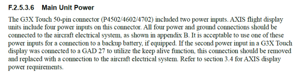
Also regarding the increase from 2 power inputs to 4 power inputs for the J1012 connector -- which note 6 to Figure B-1.1 says is for the PFD/MFD/GPS functions -- I have several questions:
1) Is the J1012 connector also for the USB-C charging (since I note the power inputs on the J1015 connector are only needed for the GDU116C/NC units per note 8 to Figure B-1.1)?
2) The paragraph above says that if you have a backup battery, you can put it into one of the J1012 power inputs. Does that mean that any one of these inputs can power all PFD/MFD/GPS functions, or is there reduced functionality if only running on one input through the backup battery in the event of electrical system failure? Assuming the answer is all these functions can be powered on one input, then what's the purpose of 4 vs 2 power inputs since 1 extra input would solve for redundancy?
3) Is the GPS functionality referred to in note 6 the built in IFR GPS that comes with the C/NC units or the built in VFR GPS that comes with the Bx unit? If IFR GPS, then are all four inputs still needed for the B units?
4) If all four are truly needed, do they all equally draw the same amount of current? The main reason I ask is because my existing GDU460 wiring is two 22AWG runs, one on a 5A breaker and one on a 5A fuse (fed from the e-bus to which the GAD27 keep alive power flows). Ideally I could keep those two runs and just add two more that are 20AWG.
5) What does Garmin recommend for the breaker size that all four inputs are tied to?
6) Usually when I see splicing like that it is a bigger wire run that is stepped down in gauge to fit the dsub pins. Does Garmin recommend a larger gauge between the breakers and the pin splice?
J1012 Connector:

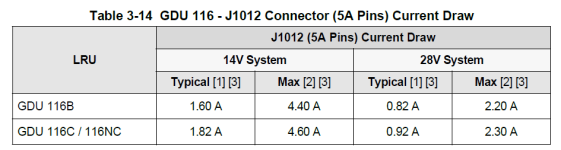
I note the increase in max draw over the G3X's 2A at 14V:
The installation manual says that if you used the GAD 27 keep alive function with G3X that you should disconnect this and connect the Axis flight display directly to the electrical system. Without the GAD 27 or a backup battery, does the Axis display have some sort of brownout protection that will keep the Axis display powered when cranking the engine? If not, does Garmin recommend a backup battery?
Also regarding the increase from 2 power inputs to 4 power inputs for the J1012 connector -- which note 6 to Figure B-1.1 says is for the PFD/MFD/GPS functions -- I have several questions:
1) Is the J1012 connector also for the USB-C charging (since I note the power inputs on the J1015 connector are only needed for the GDU116C/NC units per note 8 to Figure B-1.1)?
2) The paragraph above says that if you have a backup battery, you can put it into one of the J1012 power inputs. Does that mean that any one of these inputs can power all PFD/MFD/GPS functions, or is there reduced functionality if only running on one input through the backup battery in the event of electrical system failure? Assuming the answer is all these functions can be powered on one input, then what's the purpose of 4 vs 2 power inputs since 1 extra input would solve for redundancy?
3) Is the GPS functionality referred to in note 6 the built in IFR GPS that comes with the C/NC units or the built in VFR GPS that comes with the Bx unit? If IFR GPS, then are all four inputs still needed for the B units?
4) If all four are truly needed, do they all equally draw the same amount of current? The main reason I ask is because my existing GDU460 wiring is two 22AWG runs, one on a 5A breaker and one on a 5A fuse (fed from the e-bus to which the GAD27 keep alive power flows). Ideally I could keep those two runs and just add two more that are 20AWG.
5) What does Garmin recommend for the breaker size that all four inputs are tied to?
6) Usually when I see splicing like that it is a bigger wire run that is stepped down in gauge to fit the dsub pins. Does Garmin recommend a larger gauge between the breakers and the pin splice?
J1012 Connector:
I note the increase in max draw over the G3X's 2A at 14V:
Last edited:


