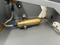
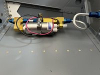
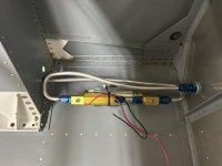
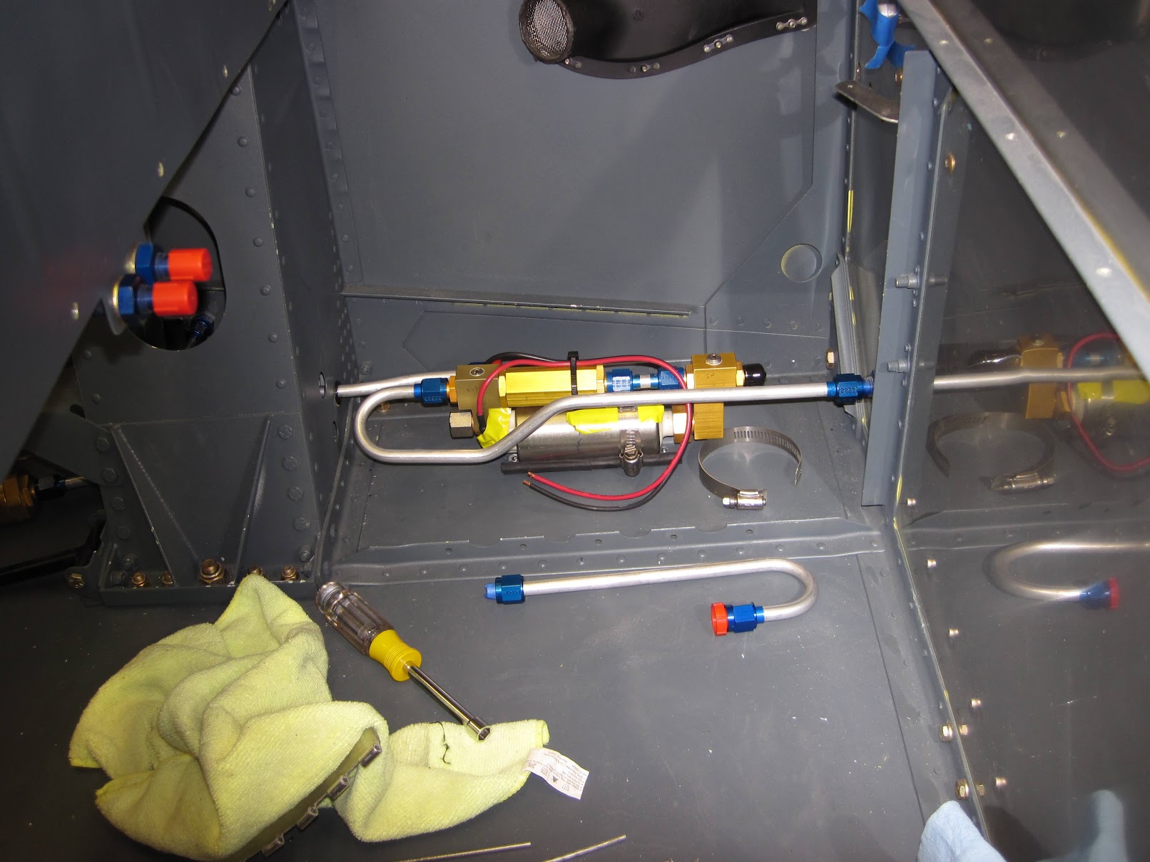
I didn’t like my first iteration of left cockpit fuel lines. So I remade and reshaped them. I’m 180 challenged with my bender. I’ve seen photos of the pump backwards from the way I did it and longer tubes with 180s on the ends. The line between the filter and pump will be nearly straight. I don’t think the gas cares if it makes a 180 before and a 180 after the pump or a 360 after the pump. But I’m surrendering to constructive criticism!!!!

Van's Air Force
You are using an out of date browser. It may not display this or other websites correctly.
You should upgrade or use an alternative browser.
You should upgrade or use an alternative browser.
Fuel line with airflow performance filter and pump
- Thread starter JDA_BTR
- Start date

scsmith
Well Known Member
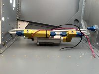
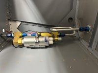
And this is the alternative didn’t finish the ends but you get the drift.
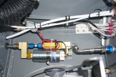
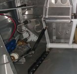
I did it kind of like this picture, but also put the fuel filter next to the pump, on a separate cradle mount. My main reason for doing it this way was to have as long a straght run into and out of my FloScan sensor, which sits in the middle of the long line running forward after the 180 after the pump.
My FloScan does read a bit high when the boost pump is on, but I prefer that to having it mounted between the servo and spider, sitting on top of the engine, as some folks do.
N804RV
Well Known Member
TS Flightlines supplies a full-flow 90deg elbow and braided line that fits perfect from the pump to the firewall.
I had decided I wanted to bend my own hard lines for everythig. But, I was so impressed with that one full-flow 90 and braided line solution I decided to use it, but make hardline for everything else.
I had decided I wanted to bend my own hard lines for everythig. But, I was so impressed with that one full-flow 90 and braided line solution I decided to use it, but make hardline for everything else.
Don't fear the bends
There are a lot of considerations, and of course reducing the chance of vapor lock and air leaks are probably the most important. Next comes ease of maintenance, since you'll be checking/cleaning this filter a lot.
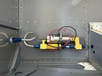
Here's how I did it. I have an aeromotive filter and an andair pump, which are not as well-integrated as the airflowperformance solution.
Just to give you another data point.
http://www.rv8.ch/andair-fuel-pump-upgrade/

There are a lot of considerations, and of course reducing the chance of vapor lock and air leaks are probably the most important. Next comes ease of maintenance, since you'll be checking/cleaning this filter a lot.
Here's how I did it. I have an aeromotive filter and an andair pump, which are not as well-integrated as the airflowperformance solution.
Just to give you another data point.
http://www.rv8.ch/andair-fuel-pump-upgrade/
I didn’t like my first iteration of left cockpit fuel lines. So I remade and reshaped them. I’m 180 challenged with my bender. I’ve seen photos of the pump backwards from the way I did it and longer tubes with 180s on the ends. The line between the filter and pump will be nearly straight. I don’t think the gas cares if it makes a 180 before and a 180 after the pump or a 360 after the pump. But I’m surrendering to constructive criticism!!!!
I just did this as well (replacing a fully plumbed andair system) and mine looks very similar to yours. Don't forget to clear the plumbing line to the right tank at the spar too.
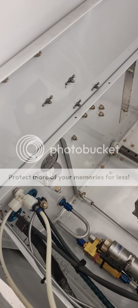
Dudley, you have to open the holes in the gear towers to allow the nuts to pass through. No, we dont use reusable hose ends in that area, infact very few. Originally the holes were for snap bushings and 3/8 OD aluminum tube, so get some AN931-7-11 grommets and open the holes up just enough to allow the nuts to pass. The 7-11 grommets are TIGHT--8-13 grommets may be better.
Tom
Tom
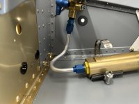
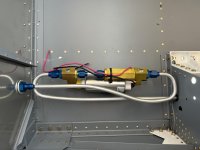
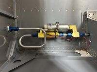
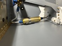
Here is what I ended up with. The bend off the filter into the gear box was a little tough and then so was the flare on the pump inlet. I got a better tube bender and made an improved pump outlet to firewall compared to what I started with. I thought someone would enjoy a pic of the boneyard.
Attachments
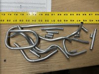
Yeah----the 368 wont bend a 180* without some modifications.
Tom
Tom
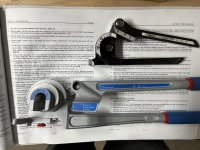
Most of the inexpensive benders can bend a 180*, most are limited to about 120*-135*. The other issue is that once the tube is bent, how do you get the flare close to the bend?
Well, if you flare the tube first, then you are limited to 1.75-2.0 inches from the flare to the bend centerline. Unless you cheat .
.
The other part of this is that most builders have a Parker Roloflare, and the dies section is about 1 inch. So you have the actual distance from the start of the bend--actually where the tube bends and the dies interfere with the curve, and there the flare section of the dies are. That usually 1 inch or so.
Rigid makes a RFT37, that has a flare bar that about .625 wide. This helps to move the flare closer to the bend. The real trick is to use a bend die thats modified to allow the flare to be moved closer. Several ways to do it, inexpensively. Doesnt matter if you have a single size bender, like an Imperial 364 series, the triple header version, or something from Harbor Freight. Same idea will work for all of them. I have several hand benders modified this way just because they are fast for doing mockup stuff. At the same time, I have a modified RFT 37, with the aft side of the flare bar 'relieved' so the bar can be closer still to the bend. For our production equipment, we designed special flare dies with large counter bores so a pre-bent tube could be flared without the dies contacting the ben. Reverse is true for the CNC bender---a special short leg bend die puts the flare close to the bend centerline. ALL of this can be replicated on inexpensive hand versions.
Tom
Well, if you flare the tube first, then you are limited to 1.75-2.0 inches from the flare to the bend centerline. Unless you cheat
.The other part of this is that most builders have a Parker Roloflare, and the dies section is about 1 inch. So you have the actual distance from the start of the bend--actually where the tube bends and the dies interfere with the curve, and there the flare section of the dies are. That usually 1 inch or so.
Rigid makes a RFT37, that has a flare bar that about .625 wide. This helps to move the flare closer to the bend. The real trick is to use a bend die thats modified to allow the flare to be moved closer. Several ways to do it, inexpensively. Doesnt matter if you have a single size bender, like an Imperial 364 series, the triple header version, or something from Harbor Freight. Same idea will work for all of them. I have several hand benders modified this way just because they are fast for doing mockup stuff. At the same time, I have a modified RFT 37, with the aft side of the flare bar 'relieved' so the bar can be closer still to the bend. For our production equipment, we designed special flare dies with large counter bores so a pre-bent tube could be flared without the dies contacting the ben. Reverse is true for the CNC bender---a special short leg bend die puts the flare close to the bend centerline. ALL of this can be replicated on inexpensive hand versions.
Tom