What's new
Van's Air Force

Don't miss anything! Register now for full access to the definitive RV support community.

Feasibility of a 3D printed snorkel?

rmartingt

Well Known Member
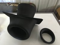
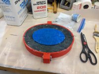
I'm getting closer to finished with my build, with about 20% of the remaining work being FWF and 75% being fiberglass (shudder). One area where these intersect is my snorkel--thanks to having an SDS throttle body and a Superior cold sump, my geometry is all screwy and I need to fab a custom intake snorkel.

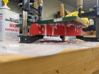
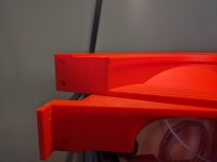
Accordingly, I mocked up a blue foam mold, coated it in tape, and started laying up glass, but fiberglass and I really don't get along. It's a nightmare, and I've been looking for ways to farm out the remaining glass work (fab, fill, and finish) in the interest of finishing this coming year and preserving my sanity.

While relating all this over coffee the other day, a good friend and former coworker suggested "well why don't you just 3D print that part? I'm sure you'd enjoy that process a lot more...". And so I got to thinking...

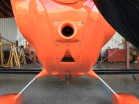
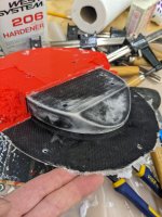
I see two big obstacles; first, I have no good way of precisely modeling the part short of a 3D scanner. Now, the last one I used was in 2008 and back then it was $80,000, but now it appears they've come way down in price just like printers. So, does anyone have recommendations on a scanner that would work around the underside of a Lycoming? Relative positioning of the ends is the really hard part to handle; I can get good measurements of the throttle body and the filter/flange area and model those properly.

Second is materials. I know my little Ender 3 can't handle the materials I'd need, but I suspect there are some high-temperature-tolerant materials that would work provided I protect enough against radiant heat from the exhaust. Anyone have suggestions here on a material/supplier?

Or am I just way off my rocker on all this?
 
I haven't flown yet, so I can't guarantee you aren't off your rocker, but if you are, I am too.

I've done a bunch of scans using an Einstar on my FWF (and some inside the cabin for trim pieces). Quality is great and process is easy -- the modeling is the hard part.

I'm did my oil cooler ducting and will do all/most of my plenum from carbon fiber reinforced nylon filament. I haven't yet done my FAB, but there's a possibility I'll end up printing that too. PA-CF is good to 400F-ish (datasheet & my testing), and from my research (including a post here), expected temperatures in the places I'm using are likely to peak in the low 200's. I'm using a Bambu X1C printer and their PAHT filament.
 
I've done a bunch of scans using an Einstar on my FWF (and some inside the cabin for trim pieces). Quality is great and process is easy -- the modeling is the hard part.
I'm fairly experienced with 3D modeling (at least in Catia), just a little rusty. It would still be more enjoyable than fiberglass...

I'm did my oil cooler ducting and will do all/most of my plenum from carbon fiber reinforced nylon filament. I haven't yet done my FAB, but there's a possibility I'll end up printing that too. PA-CF is good to 400F-ish (datasheet & my testing), and from my research (including a post here), expected temperatures in the places I'm using are likely to peak in the low 200's. I'm using a Bambu X1C printer and their PAHT filament.
Good info, thanks!
 
The problem isn't so much which scanner, but which scanner software will export a STEP file which you can edit in a CAD program.

As for material, I'd use either MJF or SLS process with PA-12 (nylon). The oil cooler duct I had made three years ago via MJF is holding up well.
 
I've used solid modeling software for about 18 years, but 3D scanning is totally new for me so take this for what it's worth. I can second the recommendation for the Einstar. That Youtube video pretty much sold me, and I'm really happy with my purchase. Earlier on I got a Revopoint pop2 which was pretty much a toy. The Einstar is impressive for the price. You need a pretty decent laptop to run it though. I use it in our business, and it's been a great investment.

Tracking and reacquire are very reliable. If you have smooth surfaces, just use markers generously. Also, the provided software gives you good tools to clean things up.

My workflow is directly from the Einstar software into Solidworks. I also went directly from Einstar to Fusion. That works too (Fusion just never really clicked for me though). I was able to import fairly large point clouds as graphics objects (in SW), and then create 3D sketches to generate my geometry. Wish I had time to use this stuff on my airplane projects. It's got tons of potential.
 
As for material, I'd use either MJF or SLS process with PA-12 (nylon). The oil cooler duct I had made three years ago via MJF is holding up well.
I remember that thread! And that's part of what got me thinking "this might actually work..."


I've used solid modeling software for about 18 years, but 3D scanning is totally new for me so take this for what it's worth. I can second the recommendation for the Einstar. That Youtube video pretty much sold me, and I'm really happy with my purchase. Earlier on I got a Revopoint pop2 which was pretty much a toy. The Einstar is impressive for the price. You need a pretty decent laptop to run it though. I use it in our business, and it's been a great investment.

Tracking and reacquire are very reliable. If you have smooth surfaces, just use markers generously. Also, the provided software gives you good tools to clean things up.

My workflow is directly from the Einstar software into Solidworks. I also went directly from Einstar to Fusion. That works too (Fusion just never really clicked for me though). I was able to import fairly large point clouds as graphics objects (in SW), and then create 3D sketches to generate my geometry. Wish I had time to use this stuff on my airplane projects. It's got tons of potential.

That's my plan, use the point clouds as references only.

Edit: The trick is going to be the computer specs apparently... I have a decent laptop but it might be really marginal for doing scanning work...
 
Last edited:
Scan

If you have an iPhone 13pro or better, you might look at Scaniverse. Seems pretty easy to use and will allow export in multiple file types including .stl.
 
Thinking out loud here for a different or complementary solution to scanning, I'd try removing the forward baffles and alternator so that with the lower cowl in place, you could reach inside from above to make cardboard templates from the throttle body flange to the lower cowl IML in a few places. Start with BL zero and then one at the RH edge of the TB flange. LH side would be mirror image. Then try making a few station line-wise.

Draw two lines on each template in X and Y (relative to axes of the airplane) that are a known length. Then digitize the templates by taking a photo of each one being careful to have the camera lens normal to the template and at a good distance. Import the jpg into catia on the correct plane and scale and orient the image to the lines on the template. Then you can make a sketch by tracing over the edges of the template with splines etc. I do this all the time in Siemens NX and works really well. That's how I did the oil cooler duct.
 
Last edited:
If you have an iPhone 13pro or better, you might look at Scaniverse. Seems pretty easy to use and will allow export in multiple file types including .stl.


This is the direction I'm going for 3D scanning. The Pro models have LIDAR which various photogrammetry apps use in conjunction with the camera to create the mesh model. There are previous threads on VAF and a web search on photogrammetry will provide software options. I don't have first hand experience yet but I just ordered an iPhone 15Pro today to try it out.
 
The problem isn't so much which scanner, but which scanner software will export a STEP file which you can edit in a CAD program.

As for material, I'd use either MJF or SLS process with PA-12 (nylon). The oil cooler duct I had made three years ago via MJF is holding up well.
Is this for a -14? How would someone go about getting a copy of your cad files for these oil cooler ducts? I definitely like the idea of having one of these to connect my square duct hole to the round hole on the baffle.
 
I don't want to rain on your parade, and I'd very much lie to see it work, but shape aside, my concern is the potential to crack since the finished product is a single layer of material. The fiberglass snorkel is 4 or 5(?) Layers of material and much less likely to have a full thickness fracture. I feel your pain with glass work though! On my plane I had a similar issue since I used the EFII system. What I did was use a short piece or high temp silicone hose attached to the throttle body, and made a 5 layer tube around a water bottle of the correct diameter to transition from hose to the snorkel. I assembled and did the finish glass work with everything mounted to the plane. Of course I did look like a weirdo walking around the store trying various plastic bottles fitment to the hose!
 
Is this for a -14? How would someone go about getting a copy of your cad files for these oil cooler ducts? I definitely like the idea of having one of these to connect my square duct hole to the round hole on the baffle.
That duct is installed on my -6, but that doesn't really matter. Send me an email to hgerhardt [at] planekool [dot] com and request the duct files. Be advised that the oil cooler I sized the duct to is a SW 10599R. If yours is smaller or bigger, you'll have to edit the adapter with a CAD program. I'll send you a STEP file which is editable.
 
I don't want to rain on your parade, and I'd very much lie to see it work, but shape aside, my concern is the potential to crack since the finished product is a single layer of material. The fiberglass snorkel is 4 or 5(?) Layers of material and much less likely to have a full thickness fracture. .......
The SLS and MJF process with PA-12 (nylon) makes a really tough part. It's ductile and not brittle. I've had that duct assembly on my -6 for over 3 years now and no signs of any cracks or plastic deformation, proven by checking the bolt torque periodically. Main thing is to make the wall thickness thick enough (mine's about .18"). Yes, that's 3x the thickness of what you could do in fiberglass, but the parts are small enough that the weight penalty is in ounces. I've also had an evaporator housing bolted to the forward upper RH fuselage rib for around 7 years now, and is only .07" wall thickness, and it hasn't cracked either. That housing was made via SLS PA-12.
 
That duct is installed on my -6, but that doesn't really matter. Send me an email to hgerhardt [at] planekool [dot] com and request the duct files. Be advised that the oil cooler I sized the duct to is a SW 10599R. If yours is smaller or bigger, you'll have to edit the adapter with a CAD program. I'll send you a STEP file which is editable.
Thanks! I'll respond via email to the address provided. I can massage the files if needed.

Don
 
I've made several ram air scoops for the Christen Eagle using 3D printing. I uses an FDM type machine for prototype fitup, but when it came time to make a part that would fly, I farmed the printing out to a company like Jawstec or Shapeways so that they could print it out of nylon using an SLS, or MJF machine. Hundreds of hours of use so far and it has worked great. The NACA oil cooler scoop is 3D printed as well.
 

Attachments

  • 20180315_211202604_iOS.jpg
    20180315_211202604_iOS.jpg
    1.5 MB · Views: 81
  • 20180315_221530975_iOS.jpg
    20180315_221530975_iOS.jpg
    2.2 MB · Views: 82
  • 20180708_202746551_iOS.jpg
    20180708_202746551_iOS.jpg
    1.8 MB · Views: 80
The SLS and MJF process with PA-12 (nylon) makes a really tough part. It's ductile and not brittle. I've had that duct assembly on my -6 for over 3 years now and no signs of any cracks or plastic deformation, proven by checking the bolt torque periodically. Main thing is to make the wall thickness thick enough (mine's about .18"). Yes, that's 3x the thickness of what you could do in fiberglass, but the parts are small enough that the weight penalty is in ounces. I've also had an evaporator housing bolted to the forward upper RH fuselage rib for around 7 years now, and is only .07" wall thickness, and it hasn't cracked either. That housing was made via SLS PA-12.
Interesting stuff. Good choice to use nylon or a material with a high enough heat deflection temp. I would be interested to see how the material handles the creep from the fasteners, have you had to retighten them at all? In my professional life we used brass, or aluminum inserts to handle the fastener load, but those were injection molded and of course had a knit line on the holes. I don’t believe the material used by the hobby 3D printers, which I usually ABS type material, would handle the temps plus would creep severely at elevated temps.
 
Interesting stuff. Good choice to use nylon or a material with a high enough heat deflection temp. I would be interested to see how the material handles the creep from the fasteners, have you had to retighten them at all? ...........
I used 10-32 socket-head cap screws with NAS washers into locking nutplates and I check the torque occasionally just to see if there's creep, and so far, zero. I expected to see some in the beginning at least, but didn't. Amazed how well this is working out. If there was any serious load on these parts which would require max torque on the bolts, then yes I would have installed inserts in addition to upping the flange thickness. But for this low-stress application it's not necessary.

Obviously fastener type would play a role here: I wouldn't use flat-heads as the angled bearing surface could create a wedging action causing creep.
 
FDM works great for making molds. This was my first attempt at a FAB adapter for an Ellison->Carb conversion, and there were some lessons learned, but otherwise I think it turned out great.
 

Attachments

  • PXL_20220326_215507761.jpg
    PXL_20220326_215507761.jpg
    2.6 MB · Views: 65
  • PXL_20220326_221500127.MP.jpg
    PXL_20220326_221500127.MP.jpg
    6.2 MB · Views: 67
  • PXL_20220326_222813010.jpg
    PXL_20220326_222813010.jpg
    1.2 MB · Views: 60
  • PXL_20220328_120051507.jpg
    PXL_20220328_120051507.jpg
    2.5 MB · Views: 67
Back
Top