


Van's Air Force

The definitive Van's Aircraft support community! Buying, building or flying an RV? Join our exclusive family of mentors and enthusiasts!

EFII System 32 - Bus Manager Alternator wiring

JoopSJ

Well Known Member
Friend
I need some advice here, as there is no guidance on this by the supplier:
I have the Bus Manager, Two batteries, B&C main and stby (vacuum pad driven) alternator, both with external voltage regs, LR-3D.
The drawing depics the current situation:
The Main Alt supplies power to both busses and battery 1.
Battery 2 is charged by the STBY Alt. To get that, the Bus Sense is picked-up at battery 2 positive terminal.
The problem I have with the current setup is that, when I depart with a weak Batt2 (I know I shouldn't), STBY Alt goes up to its limit of 40AMPS to charge the battery. I don't like this since I have no blow-tube on the alternator and am fearing overheating it.

I am looking for a setup so to let MAIN ALT to charge both batteries and save the STBY as a real backup, but I think it isn't possible considering the diode setup in the Bus Manager.
Anyone can share how they hooked-up two batteries and two alternators (with ext volt reg) ?
Please note that the blue diode in the schematic is removed when installing dual alternators.
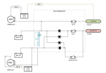
1783351158187.png
 
I've been running a very similar set-up on my 14 now over 7 years. The diode protection allows the main alternator to feed the main bus and engine bus, but the engine bus cannot feed the main bus because of the diode protection. I would regularly turn off my stand-by alternator, and the engine bus would drop from the ~14.3 volts down to 13.8 volts and hold. The problem comes in when the primary was turned off the stand-by can't feed the main bus due to diode protection. On the 10 I installed a cross-feed contactor that would allow the engine bus to feed the main bus when switched on. Z-14 (https://bandc.com/wp-content/uploads/2018/05/001-507_z14_revB.pdf) does a good job documenting this. With the cross-feed on the back-up does feed the main bus. I believe the bus manager was designed when back-up pad mounted alternators would only output 8 amps so it was impossible to use it to feed the engine bus and main bus and if one tried you could exhaust both batteries rather quick.

If anyone has a better understanding of the Bus Manager please give your input, I'm a Chem E not an EE.
 
It sounds like - in normal operation - you are reading 14.3V on the Main bus as well as the Engine bus.
I would expect - and that's what I have - the engine bus to show 13.8V because of the voltage drop behind the diode. Or is your standby Voltage regulator set to 14.8V?
 
It sounds like - in normal operation - you are reading 14.3V on the Main bus as well as the Engine bus.
I would expect - and that's what I have - the engine bus to show 13.8V because of the voltage drop behind the diode. Or is your standby Voltage regulator set to 14.8V?
Both are set at 14.3V. If I turn off the standby regulator is drops to 13.8 volts as you said because of the voltage drop of the diodes. When the main alternator feeds the stand-by bus one will always get ~ 0.5-volt voltage drop with the stand-by alternator off. That is ok when the stand-by fails, the main will feed both busses. The issue is if the main bus fails there is no way to power the main bus as the engine bus is diode protected. Your engine stays running and that is the intent, but the main bus is running on a battery that is not being charged any longer and the clock begins before one loses primary bus avionics and lighting. The only way to run both busses at peak voltage and assume your back-up alternator can output 40 amps is to use a crosstie and the total load needs to be below 40 amps. The danger here is you don't have 2 independent busses and if something major occurs on the primary bus could affect the engine bus. My plan is to only use the cross tie on the ground to charge my main bus and get to a location (60- minute hops) to service the primary alternator.

Setting the stand-by regulator to 14.8 volts does nothing if the stand-by regulator/alternator is off. The bus will always be 0.5 volts lower than the main bus.

I believe that is how the design works but I'm sure someone on the forum could explain it better.
 
... The problem I have with the current setup is that, when I depart with a weak Batt2 (I know I shouldn't), STBY Alt goes up to its limit of 40AMPS to charge the battery. I don't like this since I have no blow-tube on the alternator and am fearing overheating it.

... Please note that the blue diode in the schematic is removed when installing dual alternators.

View attachment 122295
I would worry more about overheating the battery vs the vacuum pad alternator, especially if the battery is LiFePO4.

A B&C wound field vacuum pad alternator will put out 30+ but not 40A on a Lycoming engine. Ref near the top of my Calculations Measurements and Specs spreadsheet.

In the case of lead-acid AGM battery, 13.8V is good for slow charging a depleted battery so it will not overheat and so more alternator output is available for electrical loads.
 
Last edited:
... I believe the bus manager was designed when back-up pad mounted alternators would only output 8 amps so it was impossible to use it to feed the engine bus and main bus and if one tried you could exhaust both batteries rather quick...
If AI is correct, B&C SD-20 came out in 1995, B&C 462-H in "early 2000s", and EFII Bus Manager in 2008. This correlates with my memory.

Bob Nuckoll's Z13/8 was introduced when the B&C SD-8 permanent magnet vacuum pad alternator was the only available vacuum pad alternator.

Bob created Z101 in 2020, dual alternator single battery, it uses a wound field vacuum pad alternator with its B lead connected directly to the battery. Bob Nuckolls' intent is Z101 will be equally reliable as Z14.

Then in 2021 came the Monkworkz MZ-30 vacuum pad PM "generator" which puts out 30A at 1800 Lycoming RPM. I put MZ-30 B lead directly in the engine bus, no Bus Manager, single battery dual alternator / generator.
 
Last edited:
Put the blue diode back into the circuit. That will allow the main alternator to charge the aux battery.
Another option is to put a diode in series with the standby alternator output. That diode will limit the aux battery charging current.
 
Both are set at 14.3V. If I turn off the standby regulator is drops to 13.8 volts as you said because of the voltage drop of the diodes. When the main alternator feeds the stand-by bus one will always get ~ 0.5-volt voltage drop with the stand-by alternator off. That is ok when the stand-by fails, the main will feed both busses.
Dwight, this sounds a bit odd to me. Just trying to understand the system:
The Engine bus is always behind diodes. So I would think that if you feed 14.3 you will always have 13.8 on the bus. Unless 14.3 V is supplied directly to the the E-bus through the X-tie contactor. I have looked at the B&C schematic you referred to, but I can not visualize how this is tied to the Bus Manager. Do you have a schematic that shows that?
 
Put the blue diode back into the circuit. That will allow the main alternator to charge the aux battery.
Another option is to put a diode in series with the standby alternator output. That diode will limit the aux battery charging current.
I was always curious why the instruction is to remove the blue diode when installing dual alternators.
Is my thinking correct that, with the "blue" diode installed, the MAIN ALT will have preference and feed and charge the whole system (because it is larger?). And when it fails the STBY ALT will step in and feed the E-bus? Or will there be a conflict? (I am NOT good on electrics!)
 
For electrically dependent engine I suggest never feeding engine components from a master solenoid - as the immediate action for smoke in the cabin is to open both master soleniods. I don’t have insight into EFII loads, but with two batteries is there a way to power half the EFII from one and half from the other while keeping the fan running?

I agree with running both batteries in parallel (normal ops) and splitting them out to achieve the most reliable state in the event of a power fault. Both batteries on line for engine start is also a benefit. Same for the primary alternator charging both batteries and the standby alternator in parallel, set to pick up at some nominal voltage (e.g. 13.8vdc) below normal buss voltage (e.g.14.2vdc). Both batteries would have a master solenoid, but smaller power relays between the master solenoid and battery to feed your engine loads. Repeat for IFR avionic loads.

But shoot fire, on review I see that I just eliminated the function of our buss manager….

Carl
 
For electrically dependent engine I suggest never feeding engine components from a master solenoid - as the immediate action for smoke in the cabin is to open both master soleniods. ...
Closing the Emergency Power Switch will connect any available power source to the E-bus. So in case of smoke you can kill the master relay without stopping the fan.
 
There is substantial discussion on the EFII buss manager circuitry on this forum with a bit of searching. Might tie that search with “DanH” and see if anything pops up you can use.
 
There is substantial discussion on the EFII buss manager circuitry on this forum with a bit of searching. Might tie that search with “DanH” and see if anything pops up you can use.
Yes I know, but this thread is not about BM being a good things or not. The specific question is about the best way to connect 2 alternators.
 
Closing the Emergency Power Switch will connect any available power source to the E-bus. So in case of smoke you can kill the master relay without stopping the fan.
I agree. The drawback is this requires pilot action during an emergency to keep the fan running. So just replace the switch with two relays, one on each battery, and a three position toggle switch. Problem solved and you now have option to manually select the engine on line battery. Repeat for your avionics buss.

Carl
 
Back
Top
