


Van's Air Force

The definitive Van's Aircraft support community! Buying, building or flying an RV? Join our exclusive family of mentors and enthusiasts!

EFII System 32 - Bus Manager Alternator wiring

JoopSJ

Well Known Member
Friend
I need some advice here, as there is no guidance on this by the supplier:
I have the Bus Manager, Two batteries, B&C main and stby (vacuum pad driven) alternator, both with external voltage regs, LR-3D.
The drawing depics the current situation:
The Main Alt supplies power to both busses and battery 1.
Battery 2 is charged by the STBY Alt. To get that, the Bus Sense is picked-up at battery 2 positive terminal.
The problem I have with the current setup is that, when I depart with a weak Batt2 (I know I shouldn't), STBY Alt goes up to its limit of 40AMPS to charge the battery. I don't like this since I have no blow-tube on the alternator and am fearing overheating it.

I am looking for a setup so to let MAIN ALT to charge both batteries and save the STBY as a real backup, but I think it isn't possible considering the diode setup in the Bus Manager.
Anyone can share how they hooked-up two batteries and two alternators (with ext volt reg) ?
Please note that the blue diode in the schematic is removed when installing dual alternators.
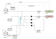

1783351158187.png
 
I've been running a very similar set-up on my 14 now over 7 years. The diode protection allows the main alternator to feed the main bus and engine bus, but the engine bus cannot feed the main bus because of the diode protection. I would regularly turn off my stand-by alternator, and the engine bus would drop from the ~14.3 volts down to 13.8 volts and hold. The problem comes in when the primary was turned off the stand-by can't feed the main bus due to diode protection. On the 10 I installed a cross-feed contactor that would allow the engine bus to feed the main bus when switched on. Z-14 (https://bandc.com/wp-content/uploads/2018/05/001-507_z14_revB.pdf) does a good job documenting this. With the cross-feed on the back-up does feed the main bus. I believe the bus manager was designed when back-up pad mounted alternators would only output 8 amps so it was impossible to use it to feed the engine bus and main bus and if one tried you could exhaust both batteries rather quick.

If anyone has a better understanding of the Bus Manager please give your input, I'm a Chem E not an EE.
 
It sounds like - in normal operation - you are reading 14.3V on the Main bus as well as the Engine bus.
I would expect - and that's what I have - the engine bus to show 13.8V because of the voltage drop behind the diode. Or is your standby Voltage regulator set to 14.8V?
 
It sounds like - in normal operation - you are reading 14.3V on the Main bus as well as the Engine bus.
I would expect - and that's what I have - the engine bus to show 13.8V because of the voltage drop behind the diode. Or is your standby Voltage regulator set to 14.8V?
Both are set at 14.3V. If I turn off the standby regulator is drops to 13.8 volts as you said because of the voltage drop of the diodes. When the main alternator feeds the stand-by bus one will always get ~ 0.5-volt voltage drop with the stand-by alternator off. That is ok when the stand-by fails, the main will feed both busses. The issue is if the main bus fails there is no way to power the main bus as the engine bus is diode protected. Your engine stays running and that is the intent, but the main bus is running on a battery that is not being charged any longer and the clock begins before one loses primary bus avionics and lighting. The only way to run both busses at peak voltage and assume your back-up alternator can output 40 amps is to use a crosstie and the total load needs to be below 40 amps. The danger here is you don't have 2 independent busses and if something major occurs on the primary bus could affect the engine bus. My plan is to only use the cross tie on the ground to charge my main bus and get to a location (60- minute hops) to service the primary alternator.

Setting the stand-by regulator to 14.8 volts does nothing if the stand-by regulator/alternator is off. The bus will always be 0.5 volts lower than the main bus.

I believe that is how the design works but I'm sure someone on the forum could explain it better.
 
Back
Top