Van's Air Force

The definitive Van's Aircraft support community! Buying, building or flying an RV? Join our exclusive family of mentors and enthusiasts!

Dynon roll servo push rod interference, RV-14 Page 57-05

WayneJ

Active Member
Ambassador
I installed the Dynon roll servo today and have an interference problem. See page 57-05. The M3441M Rod End Bearing on the Roll Servo Pushrod (57-02) contacts the W-823-AP Aileron Bellcrank Bracket and limits down aileron travel to about 6 degrees when it should be 15-17 degrees and limited by the up stop on the left (opposite) aileron. Has anyone else seen this? I vaguely remember seeing this discussed before but now I can't find it.

Thanks,
Wayne
 
Last edited:
Are you able to post a couple pictures?
I was going to add pictures but it gets more complicated and I was trying to keep it simple to see if anyone else had run into this problem. :unsure: 
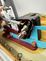
What complicates things is that I have installed the "Ball Bearing Aileron Bellcrank Kit" from Sky Designs. I modified the W-823_AP bracket and it I have mounted it two ways.
Here, mounted on the bottom side of the aileron bracket it interferes with the rod end. IMG_0576.jpeg

Here, mounted on the top side of the aileron bracket it interferes with the AN509-10R18 screw head.
IMG_0580.jpeg
In both cases it is mounted to the same holes on the servo as in the stock installation. Because of that fact I don't see why this problem wouldn't be the same with the stock configuration. This is why I was assuming others must have had the same problem. Any comments or ideas would be greatly appreciated.
 
One thing I can see is you need to move the rod-end bearing to the outside of the servo control arm. After you move it outside, you Also you need to find a shorter bolt because there are too many threads showing.
 

Attachments

  • 1727711189764.jpeg
    1727711189764.jpeg
    866.2 KB · Views: 32
It appears that it’s hitting the rod end bearing because the modified W-00823-AP is bolted to the outside of the Sky Design bracket and it looks like there are square spacers standing it off even more. Is the Sky Design W-00823-AP (blue) bracket .063? That’s what the oem bracket is and might be why it’s hitting the screw when mounted against the servo, second picture.
I like the idea of the ball bearings in this design but they should have supplied that bracket with the square hole, as in the oem.
If you go with moving the rod end bearing to the outside, you’ll have to make a longer CS-00020 standoff.
I would remove the blue modified W-00823 and mount it to the adjacent rib. Its only purpose is to hold that connector. Or abandon the bracket, drill a couple small holes in the adjacent rib and tie wrap the connector to the rib. I’m not a fan of the longer CS-00020 standoff and the unnecessary leverage.
Did you use longer AN3 bolts to attach the servo? That’s a lot more stack up than the original .063 bracket.
The blue W-823-AP bracket is the oem part that I cut down/modified to utilize the Molex mounting feature and is .063" thick. The bolt holes are the original holes so the left/right relationship is the same as stock. Mounting the rod end bearing to the outside of the servo arm is a valid idea except for the added length needed for the CS-00020. I'm not a fan of that either altho it looks like that is what is done on the RV-10. The RV-14 plans have it mounted as in my pictures.
IMG_0599.jpeg
The square spacers are part of the Sky Designs kit for bolt head clearance because of the 1/4" fillet radius on the red bracket.

I agree with the comments regarding bolt lengths and number threads showing. I am taking that into account for final assembly.

I may need to eliminate the blue W-823_AP (blue) bracket and support the connector in another way but this should work. I am surprised that no one else has run into this same problem. Seems to me that the problem would exist with the stock setup. I have not contacted Van's about this.

Maybe someone can post pictures of their installation.

Thanks for the input!
 
I'm still battling this interference problem. I have removed the W-823_AP (blue) bracket. But now the locknut on the Roll Servo Pushrod binds/contacts the 1" dia hub that the servo arm mounts to. This is in effect a hard stop for down aileron travel but is still short of the minimum down travel in the "RV-14 / 14A Control Deflection Limits" document.

After talking to Van's support yesterday it seems I may be overthinking this. I am doing this servo installation now because of the easy access with the wing in the rack and without the bottom skin on. Van's suggested completing the assembly per the KAI. Then when the wings are installed and the aileron system is fully connected, the hard stops will limit travel. Each wing has a hard up stop for aileron travel which also acts as the down stop for the opposite aileron. The assumption/hope is that there will not be any interference if assembled as instructed.

IMG_0674.jpegIMG_0675.jpeg

What's giving me heartburn is the Deflection Limits Document. It's possible this is an obsolete document. I don't remember how I found it. It doesn't seem to be in my KAI although it can be found by searching Van's website.

IMG_0680.jpeg

So my questions to fellow builders:
  1. Has anyone experienced any interference of this sort after installing their wings?
  2. Where in the KAI is the final rigging defined? I can't find it.
  3. Is there a minimum and maximum aileron deflection defined anywhere in the KAI?
 
Your posted numbers for the aileron travel in the document look correct.

Per the VA plans, that blue bracket is snugged up against the servo face and out of the way. The red bellcrank bracket, along with the square spacers are standing the blue bracket off from the face of the servo to far and causing the collision. As they are pictured, I’d say they’re incompatible… Too late now since it’s already been cut and shortened, but when modifying the blue bracket, drilling a new pair of holes to push that molex connector window further away from the swing of the servo could have worked to keep them compatible…

As for the pushrod nut hitting the base of the servo shaft… have you confirmed the eye to eye is correct on the pushrod? I wouldn’t want that servo arm to move much further even if it could as it heads off towards an over-center condition. What’s it look like when fully deflected the opposite direction with the aileron stopped at its travel limit?
 
Back
Top