Based on this reply of yours and one earlier in this thread I'm wondering if I'm hearing that you might be suggesting that the fabric that goes up and over the crank (just aft of the spinner) should be pointed forward, not aft. (???)
Certainly not. The seal sections that lie against the upper cowl behind the spinner should point inboard.
I think the way crabandy has it (pointed aft) is correct and would get pushed tighter against the glass when pressurized. Do you see it that way?
Thanks.
Exactly right.
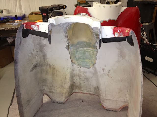
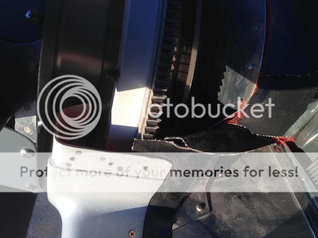
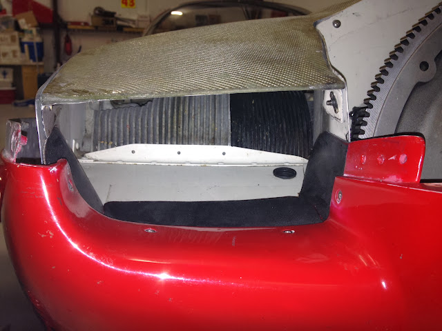
Let's look at one of the photos Bob posted. It's a good example of normal, average baffle work....which, as quantified in NASA CR3405, doesn't actually seal very well.

The seal section outlined in green is the area discussed above. Upper plenum pressure will push it flat against the cowl fiberglass, except for the big pucker in the top center (red), which is a leak. Same for the little puckers on the back wall.
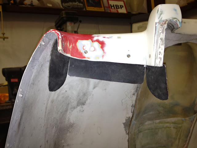
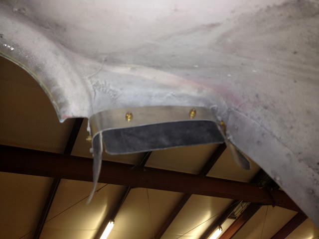
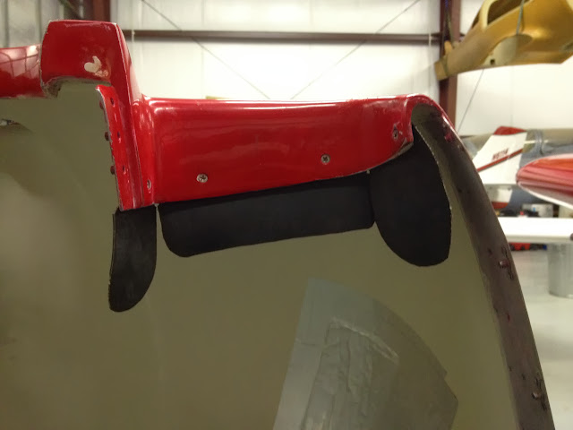
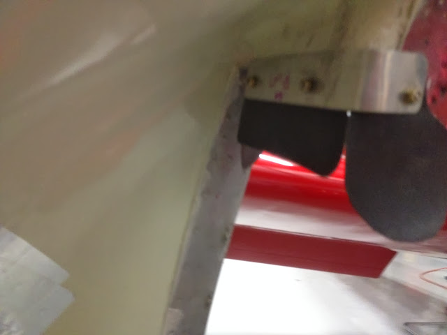
The vertical sections at each side of the inlet are a common approach, but fine examples of bad sealing. Look at the inboard section circled in red. When air pressure pushes against this section, it bends away from the fiberglass, opening a gap. What you want is seal rubber riveted to the back side of the glass, with the loose end extending rearward to overlap the aluminum and the upper seal. One piece is on the lower cowl, and one short section is on the upper cowl. Hopefully somebody will post a photo of this arrangement.
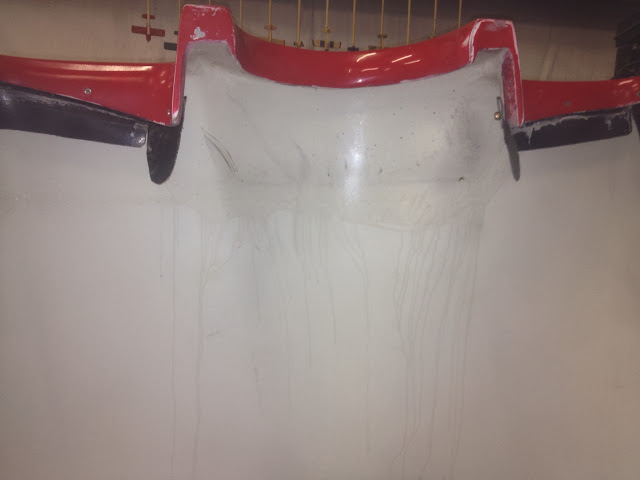
") , Good eyes as always! Those are the puckers I was talking about. The rubber was very supple there, and it almost feels as though they might be easily pressed into shape against the cowl. Wishful thinking perhaps, and I concur?very possible leak spots.
, Good eyes as always! Those are the puckers I was talking about. The rubber was very supple there, and it almost feels as though they might be easily pressed into shape against the cowl. Wishful thinking perhaps, and I concur?very possible leak spots.