Fins, washers and gaps
Wade Lively:
"From another source:
"S.J. Miley (Miss St) actually recommended making the high pressure plenum's cross-sectional area equal to that of the inlet(s), so the the plenum is not so much a plenum as a duct."
How that squares with plenum reservoir ideas I don't know."
Yea that is GREAT. I am not sure either. I guess practical aspects come into effect. Like room for the plugs and push rod tubes. I missed that quote from S.J. Miley, but tend to believe him. Hummm wounder if he is still around.
Chuck Bass
"If that is the case I would surmise that:
1) The plenum as reservoir doesn't do what we think (e.g.Atkinson's tufted video) "
Do you have a copy of this video I have not seen this tuff test.
Chuck Bass -
"IS THE CROSS SECTION THROUGH THE COOLING FINS LARGER OR SMALLER THAN INLET CROSS SECTION?" I see you want answers!

I see you are frustrated but there is no one answer. 20 ingredients going into the aerodynamic soup of calculating inlet area. There's nothing like flight test. We have good data from NASA, Barnard, Sam James and Dave Anders. Here is an example of some old NACA stuff. This looked at fins spacing and position relative to airflow:
http://naca.larc.nasa.gov/reports/1939/naca-report-674/naca-report-674.pdf (Although for a radial, one conclusion was cooling improved with tighter fin spacing, until resistance increased too much. This 1939 data helped Lycoming optimized fin spacing for good cooling and reasonable air resistance. There's a usable range of fin spacing, depth, thickness and structural considerations. OLD but interesting news. If you have energy to read them, they are interesting but too technical for most non engineers. I have an engineering degree and know just enough to get in trouble.) Here is one more of 42 on cooling fins:
http://naca.larc.nasa.gov/reports/1939/naca-report-676/naca-report-676.pdf
What's the area thru the fins to start with? Do you know? I don't. We are stuck with that fin area we have to provide the needed cooling. To get air down thru the fins to do the "WORK" of cooling needs differential pressure across those fins, to produce mass airflow to reject the heat, other wise CHT's are too high.
Cooling is a necessary evil.
The easy answer to your question is we copy what other RV'ers have done. The inlet area has been calculated for us already for our cruise speed and engine HP.
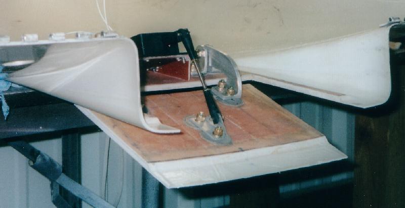
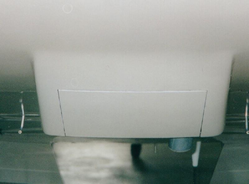
The area of the inlet for my 180HP RV w/ aluminum inlets are about 4.6" dia at the mouth and 4" at exit. They are 1.75" deep and nest into the cowl. The nozzle/diffuser uses the A-10 or -20 NASA laminar airfoil contour. They are custom inlets, not from Sam James, which does not have the same design or internal shape. My cowl is a modified stock cowl with these aluminum inlets to a custom plenum. My total inlet area is 2 * Pi/4 * (4")^2 = 25.2 in-sq, 33 sq based on mouth. How does that relate to fin area of the O360A1A? I don't know or care as long as I go fast and stays cool.
The NASA research was NOT complete and somewhat left unfinished in the early 80's. Great data and observations where made, but they did not give design details. That's where our creativity comes in. When it comes to utilizing the NASA concepts, I think Barnard's Holy Cowl (now Sam James) interpretation is very good but not perfect. I choose to make my own cowl (from a stock one) and plenum to get it the way I wanted it.
There are some excellent books on engine cooling, but don't recall the title or author's. Than there is stacks of NASA reports, many from War Time on the subject of air cooled engines. Me personally, I copied from Dave Anders and Tracy Saylor, because they showed it was a reasonable area. Lazy but smart. Know when to copy.
The racers get away with tiny inlets and fixed geometry because they are made to just go fast, not climb for 12,000 feet. So be careful who you copy and why.
The inlet is only one piece of the puzzle. The way you handle the air after that is critical.
Variable inlet geometry would be nice, but that's not really workable. Even Cessna has variable geometry in the form of cowl flaps. Why don't we? Well one it adds weight and design complexity, but it's doable. My exhaust tunnel and cowl flap would involve massive belly structure rework. It could be done, but not sure if it's practical or worth it.
Looking at some of the old classic GA planes of the past you might say, geee what where they thinking. In the last two decades the standard has changed. However they did not have 20 channel engine monitors, much less one CHT. This is where LoPresti made bread and butter in his latter years, making NASA (MSU) inspired cowl mods for older factory planes:
http://www.speedmods.com/
Now the new Mooney looks like this:
http://www.mooney.com/
Lycoming Cylinders
Absolutly the fins are thicker / deeper on the (hot) exhaust port side by design. Clearly this was engineered (well), but since they where designed in the 1940's / 50's something, all those guys are gone, so we can't ask. The (cool) intake side does not need the same "fin-age" (made up a word to day mom). It does save weight and allow a more compact design. I think the Lyc design is brilliant and well thought out. Also the fin area, height, thickness and spacing has been researched to death I recall, in the 30's/40's.
There's no free lunch, you will always have some cooling drag. I don't think redesign of the fins is the key. Hey that is why the Hawker Sea Fury is the fastest plane at at Reno with a BIG radial. At least the air is going in the same direction as the fin. As was pointed out the air has to turn and go down (draft) on our little Horz opposed engine.
Van's stock baffle if fitted too high and tight on #2 & #3, will choke the air off to the lower (deeper fins) on the bottom of the cylinder. You need all the air you can get there. Kent Paser ("Speed w/ Economy) played with these gaps and got dramatic results.
The washer trick, absolutly you can control the gap and increase the flow on the #2 and more important #3 jug.
It is really a local airflow issue, that is all. You are bypassing air to get it where you want. However I suspect you are thinking bypassing the air around the fins (more baffle fin gap) air would speed up. It would reduce drag and cooling may increase to a point. A 1937 NACA report discusses baffle to fin gap:
http://naca.larc.nasa.gov/reports/1937/naca-tn-620/naca-tn-620.pdf
(be careful how you use this radial ring cowl data; also more cooling may be more drag as well.)
The washer trick works but is a little crude. It is a good way to experiment, but a better way is have baffles fit properly without shims and washers. When you add washers you tend to get leakage out the side of the lower wrapped around portion of the baffle. Some baffles have formed flanges on the edges to control the edge leakage. You can achieve the similar effect with silicone beads.
My theory is you need to have a good cooling system to start with before you can reduce cooling drag. Every little part has to work together. One small detail deficiency can ruin the efficency of the cooling system.
Mike S -
"take a look at the cowling outlet of the AR 6 in the attached link." Isn't that crazy. This is a good use for fiberglass. Every detail on these formula racers are extream. Not sure how much we can incorporate in our "daily flyer's", but agree, there are things to learn. At some point there's a balance and sacrifice for speed. These are all out racers. Cooool! (I think most formula planes are trailered to the race)